
Organic solar cell and method of manufacturing the same

a solar cell and organic technology, applied in the field of organic solar cells and a manufacturing method, can solve the problems of limiting the improvement of efficiency, a rapid increase in fuel expenses, and exhaustion of energy sources, and achieves the effects of increasing the quantity of light, high light absorption efficiency, and high efficiency

Active Publication Date: 2019-10-15
LG CHEM LTD
View PDF27 Cites 0 Cited by
  • Summary
  • Abstract
  • Description
  • Claims
  • Application Information

AI Technical Summary

Benefits of technology

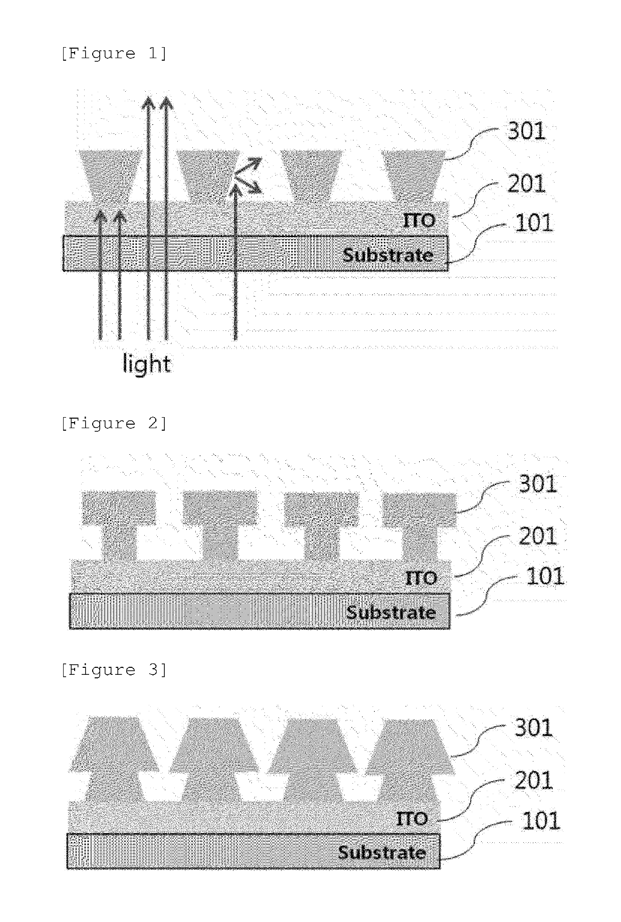
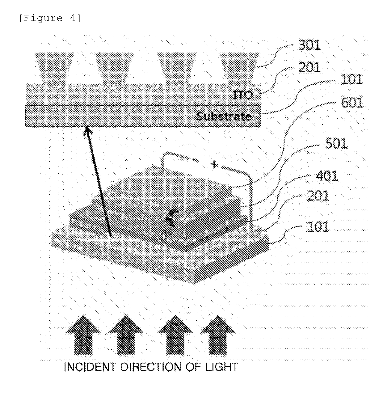
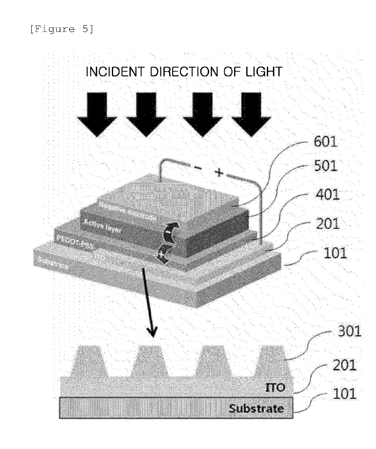
The present patent describes an organic solar cell that has improved light absorption efficiency by increasing the amount of light that reaches the photoactive layer and by allowing light to be re-absorbed. Additionally, the organic solar cell has a high fill factor when manufacturing a large-area device by reducing resistance of the electrode.

Problems solved by technology

Due to a rapidly increased energy consumption amount and a limited reserve amount of an energy source, problems such as a rapid increase in fuel expenses and exhaustion of the energy source have reached a critical level.
Various donor and acceptor materials have been reported, but it is difficult to expect efficiency of 3% or more except for P3HT / PCBM, PCPDTBT / PCBM, or the like.
For example, in the case where a thickness of the photoactive layer is increased in order to increase light absorption, due to a reduction in charge mobility and electric field, since re-combination of charges is increased, there is a limit in improving efficiency, and in the case where a large-area cell is manufactured in order to embody a module, due to an increase in resistance of a transparent electrode, an efficiency reduction (cell to module loss) significantly occurs.

Method used


Image

  • Organic solar cell and method of manufacturing the same
  • Organic solar cell and method of manufacturing the same
  • Organic solar cell and method of manufacturing the same

Examples


preparation example 1

[0119]On the glass / ITO / Cu / Al substrate where ITO, Cu, and Al were sequentially deposited in the thickness of 150 nm, 200 nm, and 30 nm, respectively, on the glass, the hexagonal mesh pattern having the line width of about 7 μm was formed by the photolithography method using the novolac-based positive photoresist (PR). Thereafter, after etching was performed by using the phosphoric acid / nitric acid / acetic acid-based etchant at 45° C. for 9 seconds, the shape was observed by the optical microscope, and the cross-section was observed by the scanning electron microscope (SEM). Thereafter, the novolac photoresist was removed by using the organic amine-based stripper to manufacture the transparent electrode including the ITO / inverse taper metal auxiliary electrode.

[0120]FIG. 7 is an optical microscope picture immediately after PR patterning is performed by the method of Preparation Example 1, and FIG. 8 is a SEM cross-sectional picture immediately after PR patterning and Cu / Al etching are...

example 1

[0121]On the transparent electrode including the metal auxiliary electrode, in which the ratio of the line widths of the lower surface and the upper surface is 1:2, manufactured by the same method as Preparation Example 1, the PEDOT:PSS solution was applied, and heat treatment was then performed at 140° C. for 15 minutes. After the solution of P3HT and PCBM mixed at the ratio of 1:0.7 was applied on PEDOT:PSS to form the photoactive layer of about 220 nm, the Al electrode was deposited on the photoactive layer under 1×10⁻⁷ torr, and then subjected to heat treatment at 150° C. for 10 minutes to manufacture the organic solar cell.

example 2

[0122]On the transparent electrode including the metal auxiliary electrode, in which the ratio of the line widths of the lower surface and the upper surface is 1:3, manufactured by the same method as Preparation Example 1, the PEDOT:PSS solution was applied, and heat treatment was then performed at 140° C. for 15 minutes. After the solution of P3HT and PCBM mixed at the ratio of 1:0.7 was applied on PEDOT:PSS to form the photoactive layer of about 220 nm, the Al electrode was deposited on the photoactive layer under 1×10⁷ torr, and then subjected to heat treatment at 150° C. for 10 minutes to manufacture the organic solar cell.


PUM


Abstract

The present specification provides an organic solar cell and a method of manufacturing the same.

Description

TECHNICAL FIELD[0001]This application is a National Stage Entry of International Application No. PCT / KR2014 / 005225, filed Jun. 13, 2014, and claims the benefit of and priority to Korean Application No. 10-2013-0068553 filed in the Korean Intellectual Property Office on Jun. 14, 2013, both of which are incorporated herein by reference in their entirety for all purposes as if fully set forth herein.[0002]The present specification relates to an organic solar cell and a method of manufacturing the same.BACKGROUND ART[0003]Due to a rapidly increased energy consumption amount and a limited reserve amount of an energy source, problems such as a rapid increase in fuel expenses and exhaustion of the energy source have reached a critical level. Further, together with this, regulations by individual countries on discharging of carbon dioxide have been further tightened. As a countermeasure on these problems, research for natural energy which is capable of being regenerated and is near inexhaus...

Claims


Application Information

Patent Timeline
Patent Type & Authority Patents(United States)
IPC IPC(8): H01L51/44H01L51/42H01L51/00H10K99/00
CPCY02E10/549Y02P70/50H10K85/1135H10K30/30H10K30/83H10K30/87H10K2102/103H10K30/50H10K30/00H10K30/82
Inventor LEE, HANGKENSEONG, JIEHYUNLEE, JAECHOLCHOI, JEONG MINJANG, SONGRIMLEE, SEUNG HEONJANG, SONG HO
Owner LG CHEM LTD
Learn More