
Energy storage system and operation method thereof

a technology of energy storage and operation method, which is applied in the field of energy storage system and an operation method thereof, can solve the problems of difficulty in rapid adjustment to large power fluctuations, high cost of the overall device, and the inability to properly control frequent power fluctuations in the system, so as to improve the regulation speed and performance of the system, reduce the number of high-current charges, and improve the life of the battery

Active Publication Date: 2020-01-28
WUHAN INSTITUTE OF TECHNOLOGY +2
View PDF1 Cites 0 Cited by
  • Summary
  • Abstract
  • Description
  • Claims
  • Application Information

AI Technical Summary

Benefits of technology

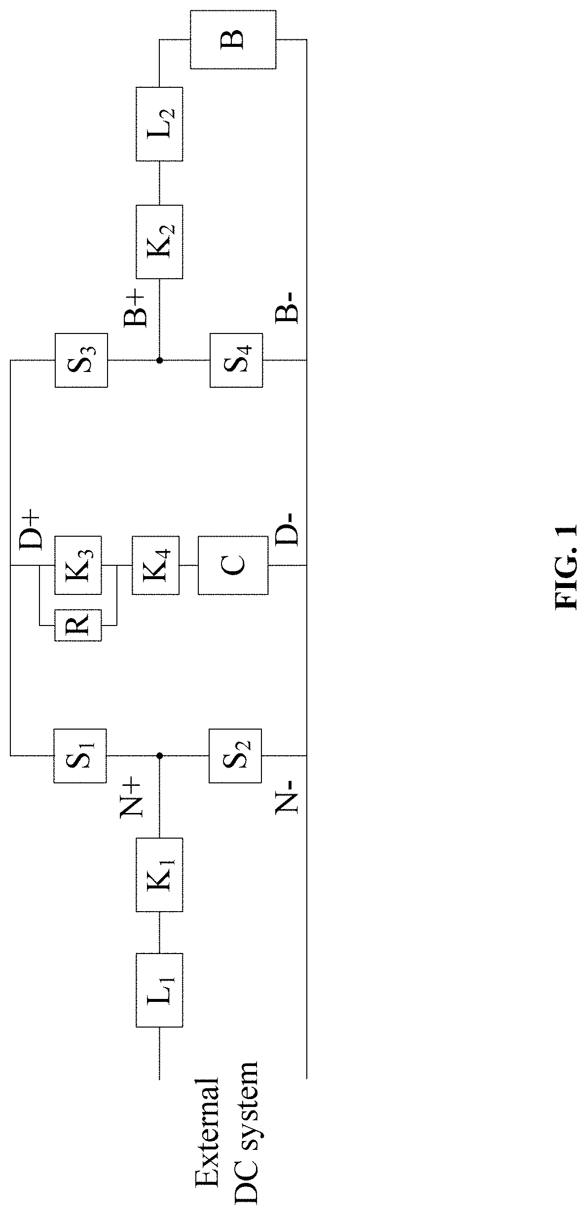
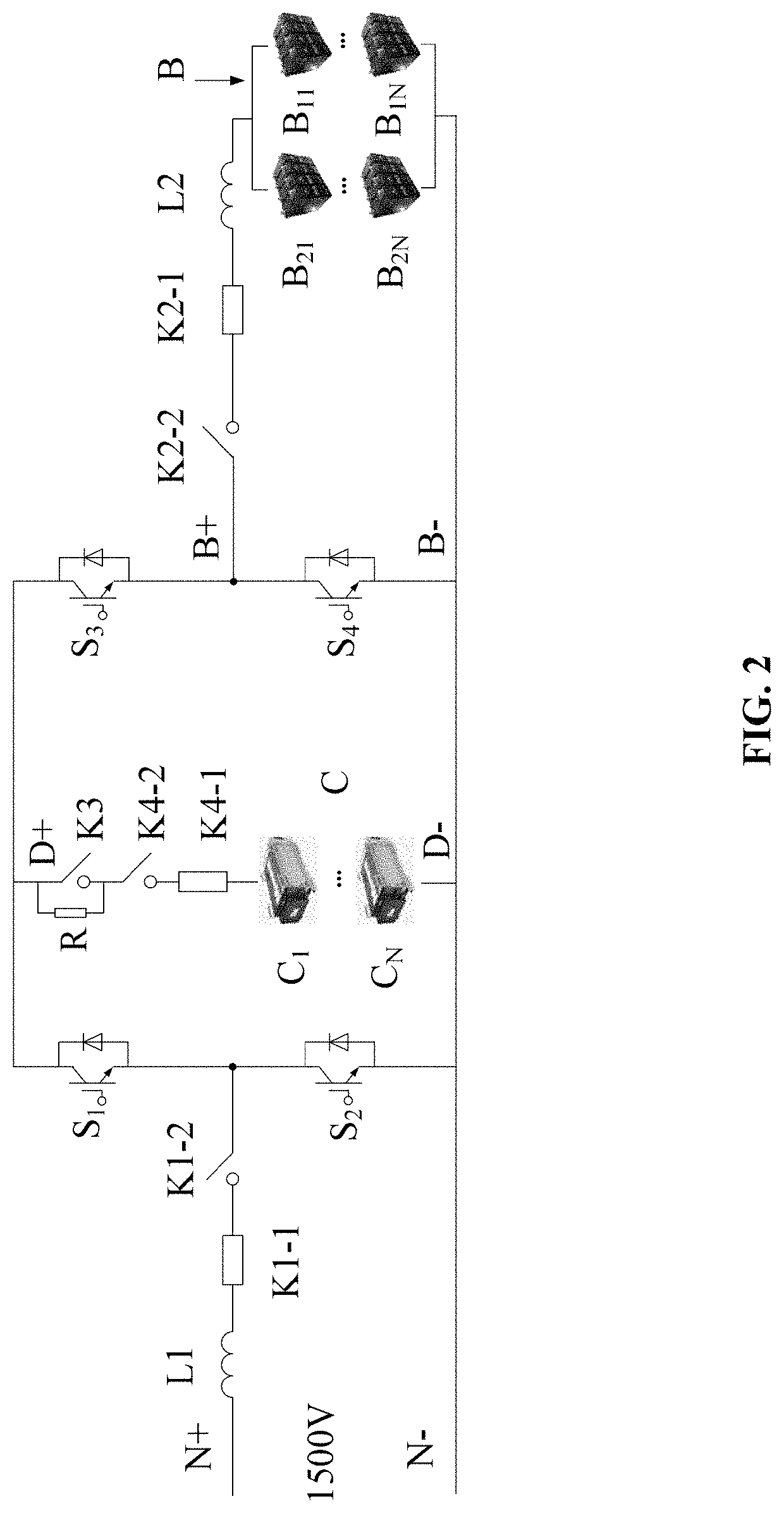
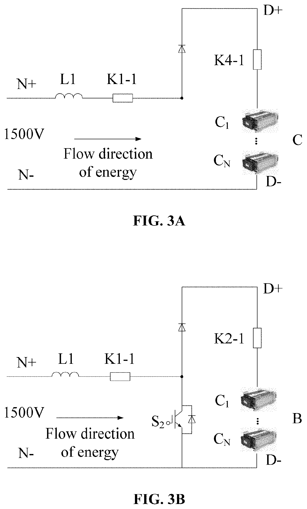
The present patent text describes an energy storage system that includes a super-capacitor placed before a battery to absorb and release frequent and high power through proper control. This improves the regulation speed and performance of the system, reduces the number of high-current charges and discharges of the battery, and improves the lifetime of the battery. The system also includes a boost circuit for efficient energy storage and release over a wider voltage range, a buck-boost circuit for reducing the number of battery cells connected in series, and a pre-charge circuit for protecting devices from damage and limiting fault current. The invention has high integration, a compact structure, and relatively simple control, and makes better use of the characteristics of both energy storage components compared with a parallel connection.

Problems solved by technology

(1) In high voltage and high power situations, in consideration of costs, batteries are used as energy storage components, and new and expensive energy storage components are only used in some demonstration projects. Devices that use batteries as energy storage components mainly aim at providing backup support to the system in case of emergencies and grid failures, or enabling load shifting so as to reduce the peak demand of electricity and capital investment in the power generation system. However, in this mode, it is difficult to adjust rapidly to large power fluctuations and impacts occurring in the power supply.
(2) The large number of batteries connected in series results in a demand for high consistency of battery parameters, which leads to a high cost of the overall device. In addition, due to battery charge and discharge cycle limits, frequent power fluctuations in the system cannot yet be properly controlled.
(3) Because the energy capacity of the super-capacitor is proportional to the square of the voltage, in some systems where the super-capacitor is directly connected in parallel to the external DC system, the energy storage capacity of the super-capacitor cannot be exploited. Also, too frequent voltage fluctuations in the external DC system, have a negative impact on the super-capacitor itself.
(4) If the battery and the super-capacitor are connected in parallel, or the battery and the super-capacitor are connected in parallel after passing through the DC / DC converter, despite a super-capacitor being added in similar systems, when frequent fluctuations in power or voltage occur in a large part of the system, the voltage and current are still applied to both energy storage components at the same time; therefore, the negative impact on the battery still exists, and it is difficult to achieve efficient energy absorption and release.
(5) The super-capacitor has a low internal resistance and an energy capacity much larger than that of normal capacitors, the magnitude and duration of impact current of the super-capacitor during power-on will far exceed that of the normal capacitors. Therefore, a pre-charging circuit with a larger power needs to be provided.

Method used


Image

  • Energy storage system and operation method thereof
  • Energy storage system and operation method thereof
  • Energy storage system and operation method thereof

Examples


application examples

[0087]The energy storage system of the present disclosure has been put to practical use on the Komatsu Model 730 E off-highway mining dump truck, which has a rated power of 1490 kW, a curb weight of 140 tons, a payload of 180 tons, a rated voltage of 1500 V for the external DC system, a rated voltage of 1800 V for the super-capacitor, a rated voltage of 450 V for the battery, and a power of 300 kW. The first and second terminals of the pre-stage bidirectional buck-boost conversion circuit shown in FIG. 1 are respectively connected to the positive and negative electrodes of a DC electric wheel power supply system for the mining truck (i.e., the external DC system referred to in the present disclosure). The brake signal and throttle signal from the mining truck are input into the present device. When the truck driver brakes, the energy storage system proceeds to (4) of the operation method described above to absorb the brake energy generated by the DC electric wheel. When the truck dr...


PUM

PropertyMeasurementUnit
voltageaaaaaaaaaa
voltage levelaaaaaaaaaa
pre-charge currentaaaaaaaaaa

Abstract

An energy storage system, including: a first switch and a first inductor connected in series and connected to a positive electrode of an external DC system; a pre-stage bidirectional buck-boost conversion circuit, the circuit including a first terminal, a second terminal, and a third terminal; a pre-charge circuit, a fourth switch, and a super-capacitor sequentially connected in series, two terminals of a series structure resulting therefrom being connected to the third terminal of the pre-stage bidirectional buck-boost conversion circuit and the negative electrode of the external DC system, respectively; a post-stage bidirectional buck-boost conversion circuit, the circuit including a first terminal, a second terminal, and a third terminal; and a battery, a second switch, and a second inductor connected in series.

Description

CROSS-REFERENCE TO RELATED APPLICATIONS[0001]Pursuant to 35 U.S.C. § 119 and the Paris Convention Treaty, this application claims foreign priority to Chinese Patent Application No. 201611108194.2 filed Dec. 6, 2016, the contents of which and any intervening amendments thereto are incorporated herein by reference. Inquiries from the public to applicants or assignees concerning this document or the related applications should be directed to: Matthias Scholl P.C., Attn.: Dr. Matthias Scholl Esq., 245 First Street, 18th Floor, and Cambridge, Mass. 02142.BACKGROUND OF THE INVENTIONField of the Invention[0002]The present disclosure relates to the field of storage and release of electric energy, and, in particular, to an energy storage system and an operation method thereof.Description of the Related Art[0003]To improve the performance of energy storage devices, some researchers have proposed to use a combination of a battery and a super-capacitor. The main topology is of a battery and a s...

Claims


Application Information

Patent Timeline
Patent Type & Authority Patents(United States)
IPC IPC(8): H02J7/34H02M1/00H02M1/36H01M10/42H02M3/158
CPCH02J7/34H02J7/345H01M10/4264H02M3/1582H02M1/36H02M3/158H02M2001/007H02M1/007Y02E60/10
Inventor LIU, JIANGUAN, ZENGLUNZHANG, ZHONGWENLIU, RUCHENGYAN, BINGLOU, ZHENSHENWANG, YANGLIU, XIAOHUQIN, SHIHONGWEN, XIAOLINGLI, ZICHENG
Owner WUHAN INSTITUTE OF TECHNOLOGY
Learn More