
Filter element for decomposing contaminants, system for decomposing contaminants and method using the system

a filter element and contaminants technology, applied in the field of photocatalytic elements, can solve the problems of inability of conventional filter units to remove materials that exist in gas phases, harmful gases and malodorant components, adsorption capability, etc., and achieve the effect of extending the stock life of ethylene-sensitive plants

Active Publication Date: 2020-02-04
NITTO DENKO CORP
View PDF93 Cites 4 Cited by
  • Summary
  • Abstract
  • Description
  • Claims
  • Application Information

AI Technical Summary

Benefits of technology

[0009]In accordance with the purposes of the present invention, as embodied and broadly described herein, embodiments of the present invention includes a photocatalytic element for decomposing contaminants, including, but not limited volatile organic compounds and / or gases, inorganic compounds and or gases, and a method of purifying the air by decomposing contaminants in the air, and a method of extending the stock life of ethylene-sensitive plants by reducing the concentration of ethylene gas using said photocatalytic element. Herein, the photocatalytic element refers to an element that comprises at least a photocatalytic composition.
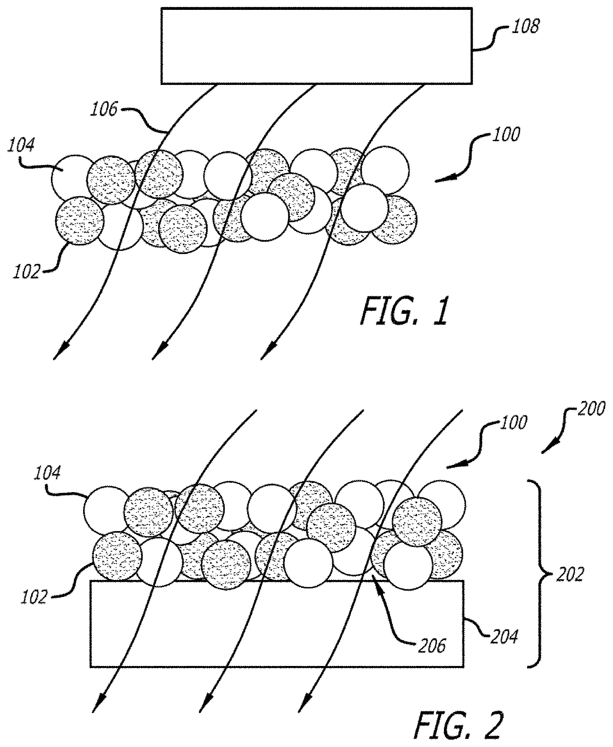
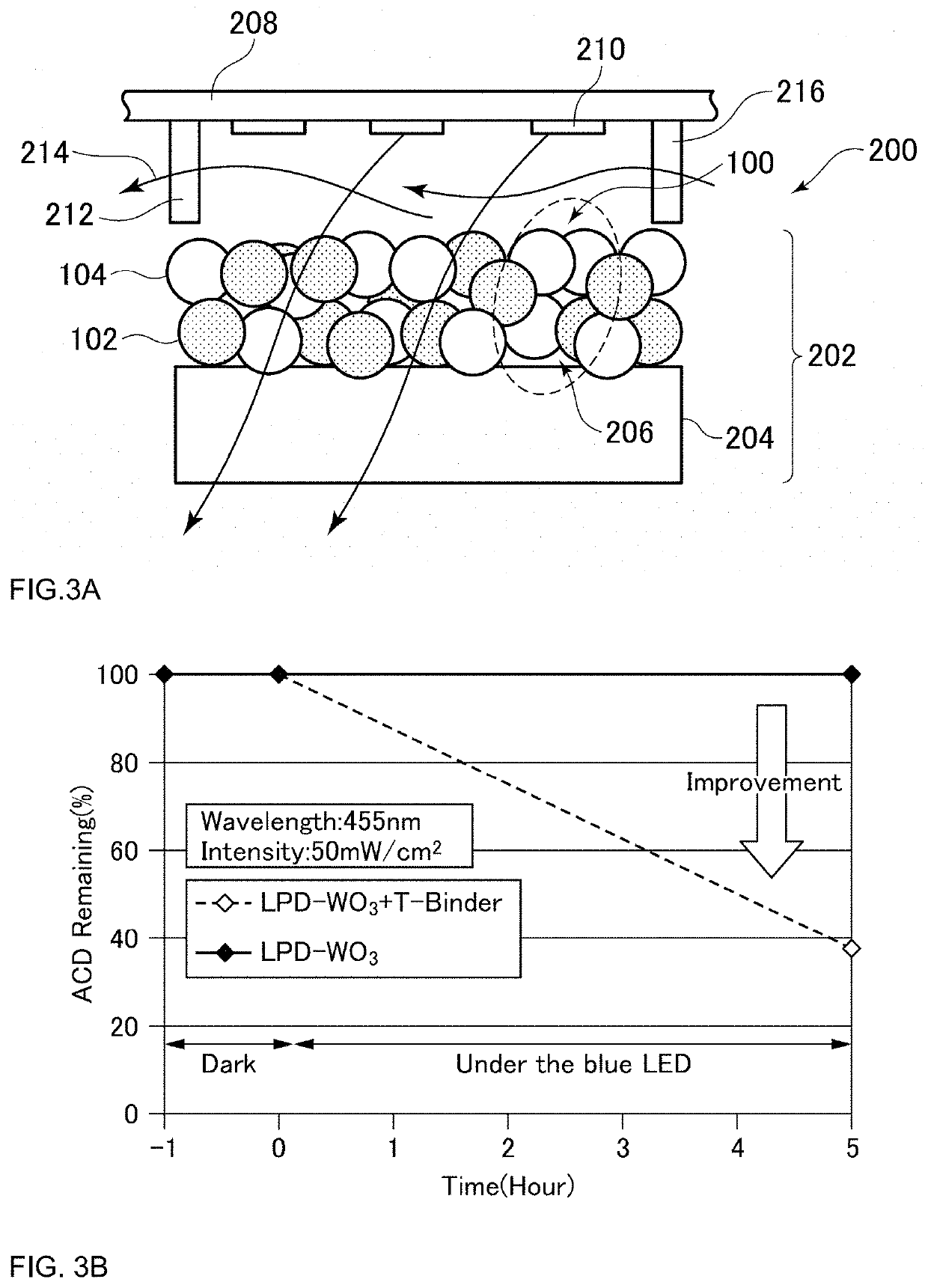
[0010]The embodiments include a filter element for decomposing contaminants comprising a substrate and a photocatalytic composition comprising at least a photocatalyst, which may be used to effectively reduce contaminants in the air by decomposing and / or oxidizing a contaminant when the photocatalytic element is illuminated by light and in contact with a contaminant. The embodiments can be more effective at reducing volatile organic compounds and / or gases, inorganic compounds and or gases levels, e.g., ethylene, than the filters and compositions used in the prior art. In some embodiments, the photocatalytic composition may be disposed over a substrate. In some embodiments, the substrate is a gas permeable support. In some embodiments, the photocatalyst shows visible light responsiveness. In some embodiments, said photocatalyst comprises WO3, TiO2, or Ti(O,C,N)2:Sn. In some embodiments, the photocatalytic composition further comprising a co-catalyst. In some embodiments, said co-catalyst comprises anatase TiO2, SrTiO3, KTaO3, or KNbO3. In some embodiments, said co-catalyst comprises In2O5, Ta2O5, anatase TiO2, rutile TiO2, a combination of anatase and rutile TiO2, or CeO2. In some embodiments, the photocatalyst contains WO3, and the co-catalyst contains CeO2. In some embodiments, the photocatalyst contains TiO2 or SnO2, the co-catalyst contains Cu2O and / or CuO, and the co-catalyst is supported on the photocatalyst. In some embodiments, the filter element further comprises a fluororesin porous layer laminated on at least one surface of the substrate, and the photocatalytic composition is disposed on the fluororesin porous layer. In some embodiments, a fluororesin constituting the fluororesin porous layer contains polytetrafluoroethylene. In some embodiments, the photocatalytic composition is formed on the fluororesin porous layer through an aerosol deposition method.
[0013]The embodiments comprise a method of placing the system in atmospheric communication with ethylene-sensitive plants and illuminating the photocatalytic element with light such that the photocatalytic element decomposes and / or oxidizes ambient ethylene, reducing ethylene levels in the air.

Problems solved by technology

While such filter units with conventional filter elements can remove powder dust at the intended design efficiency, conventional filter units are incapable of removing materials that exist in a gas phase, including, for example, harmful gases such as volatile organic compounds (VOCs), and malodorant components that produce a bad odor.
Herein, it has been known that such harmful gases and malodorant components can be adsorbed and removed with the use of activated carbon.
However, because the adsorption capability of activated carbon is limited, the activated carbon needs to be replaced every time the adsorption reaches saturation.
If left unreplaced in the saturated state, the activated carbon would no longer be able to sufficiently adsorb and remove harmful gases and malodorant components, and these materials will respread through the filter unit.
Oxidizers in the prior art suffer from a similar drawback to filters in that they are consumable; they are used up as they work and must be replaced from time to time to maintain their efficacy.

Method used


Image

  • Filter element for decomposing contaminants, system for decomposing contaminants and method using the system
  • Filter element for decomposing contaminants, system for decomposing contaminants and method using the system
  • Filter element for decomposing contaminants, system for decomposing contaminants and method using the system

Examples


example 1

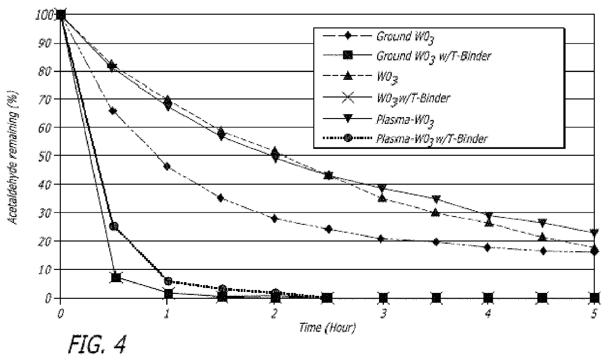
[0223]WO3 photocatalyst (200 mg), as prepared according to the method described earlier in this disclosure, was added to water. The resulting dispersion was then added to 740 mg of CeO2 sol (Nissan Chemical America, Houston, Tex., USA, NanoUse CE-20B). The mole ratio of CeO2 and WO3 was chosen to be 1:1 (50 molar % to 50 molar %). Then a sufficient amount of RO (reverse osmosis treated) water (800 mg) was added to the resulting dispersion in order to make a coating solution which is about 20 wt % solid materials in water. The resulting dispersion was homogenized using an ultrasonic homogenizer. A glass substrate (50 mm×75 mm) was coated with the prepared resultant by using a spin coater (1200 rpm / 40 sec). The coated substrate was heated for about 2 minutes at about 120° C. The resulting coated substrate was transparent (about 86% at about 555 nm). Photocatalytic activity was determined by monitoring the acetaldehyde degradation ratio to about 81% after 1 hour of blue light-emitting ...

example 2

[0224]Coated substrate 2 was made in a similar manner to Example 1, except that SiO2 sol (Nissan Chemical SNOWTEX O, 258 mg) was added instead of CeO2 sol. The resulting coated substrate was transparent (90% at about 555 nm). Photocatalytic activity as determined by the acetaldehyde degradation ratio was about 50% after irradiation under conditions similar to Example 1.

example 3

[0225]Coated substrate 3 was made in a similar manner to Example 1, except that SiO2 sol (Nissan-Chemical SNOWTEX 20L, 258 mg) was added instead of CeO2 sol. The resulting obtained substrate was transparent (91% at 555 nm). Photocatalytic activity as determined by the acetaldehyde degradation ratio was about 67% after irradiation under conditions similar to Example 1.


PUM

PropertyMeasurementUnit
wavelengthaaaaaaaaaa
visible wavelengthsaaaaaaaaaa
band gapaaaaaaaaaa

Abstract

Embodiments of the present invention include a filter element for decomposing contaminants including a substrate, and a photocatalytic composition comprising at least a photocatalyst. The embodiments of the present invention also includes a system for decomposing contaminants including a substrate, and a photocatalytic composition comprising at least a photocatalyst; and a method using the system.

Description

CROSS REFERENCE TO RELATED APPLICATIONS[0001]This application is a national phase of PCT / jp2014 / 068520 filed on Jul. 4, 2014, which claims the benefit under 35 U.S.C. § 119(e) to U S. Provisional Application Ser. No. 61 / 843,264 filed Jul. 5, 2013, U.S. Provisional Application Ser. No. 61 / 843,265 filed Jul. 5, 2013, U.S. Provisional Application Ser. No. 61 / 899,799 filed Nov. 4, 2013, U.S. Provisional Application Ser. No. 61 / 899,804 filed Nov. 4, 2013, U.S. Provisional Application Ser. No. 61 / 944,879 filed Feb. 26, 2014, and foreign priority Japanese Application No. 2014-113001 filed on May 30, 2014 the entire contents of all of which are hereby incorporated by reference in their entirety.TECHNICAL FIELD[0002]The present embodiments generally relate to reduction of contaminants in air. More particularly, the present embodiments pertain to a photocatalytic element for removing microbes and malodorous gases from the air using a photocatalytic composition, reducing the concentration of e...

Claims


Application Information

Patent Timeline
Patent Type & Authority Patents(United States)
IPC IPC(8): B01J35/00B01J23/888A61L9/20B01D53/86B01J23/30B01J23/34B01J23/72B01J23/14
CPCB01D53/8668B01J23/30B01J23/34B01J23/14A61L9/205B01J23/72B01J35/004B01J23/888B01D2255/802B01D2257/90B01D2255/2061B01D2255/20707B01D2255/20761B01D2255/20769B01D2255/20776B01D2257/7022B01D2255/2094B01D2255/2065B01D2255/2073B01D53/8687B01D2257/702B01D2257/708B01D2259/804B01J37/035B01J37/343B01J37/349B01J37/0219B01J23/835B01J35/0013B01J37/0217B01J2523/00B01J27/24B01J35/06A61L2209/14B01J2523/31B01J2523/3712B01J2523/69B01J2523/13B01J2523/57B01J2523/56B01J2523/43B01J2523/47
Inventor OZAKI, TAKASHIFUKUMURA, TAKUYAMINE, KEITAPAN, GUANGSAMBANDAN, EKAMBARAMMUKHERJEE, RAJESH
Owner NITTO DENKO CORP
Learn More