Conical nano-carbon material functionalized needle tip and preparation method therefor

a technology of conical nano-carbon materials and needle tips, which is applied in the direction of microstructural technology, microstructural devices, liquid/fluent solid measurements, etc., can solve the problems of high interface resistance and low mechanical strength, largely limits the practical application of the functionalized needle tip of the nano-carbon material, and the most of the synthetic conical nano-carbon materials have many structural defects, etc., to improve electrical conductivity, improve the effect of electrical conductivity and contamination of nano-materials

Active Publication Date: 2020-11-03
THE NAT CENT FOR NANOSCI & TECH NCNST OF CHINA
View PDF21 Cites 6 Cited by
  • Summary
  • Abstract
  • Description
  • Claims
  • Application Information

AI Technical Summary

Benefits of technology

[0039]The conical nano material functionalized needle tip prepared by the method of the invention has good interface contact, and the orientation of the conical nano-material is matched with the axial direction of the metal needle tip. At the same time, contamination of nano-materials during the deposition of fixed materials such as carbon or tungsten in other preparation methods is avoided. The conical nano-carbon material functionalized needle tip prepared under optimal conditions has a metal carbide bonded interface. Due to the excellent electrical conductivity and hardness of the metal carbide, the conical nano-carbon material functionalized needle tip prepared by the method of the present invention has better electrical conductivity and higher mechanical strength than the existing functionalized needle tips.

Problems solved by technology

The nano-material functionalized needle tip prepared by this method has high interface resistance and low mechanical strength, which largely limits the practical application of the nano material functionalized needle tip.
In addition, up to now, all the preparation methods of the needle tip cannot directly ensure that the orientation of the one-dimensional / quasi-one-dimensional nano-materials is consistent with the axial direction of the metal needle tip, which becomes a technical difficulty for the wide application of the nano-materials functionalized needle tip[2, 6].
However, most of the synthetic conical nano-carbon materials have many structural defects, and the tail of the cone is closely connected with the substrate material, such that they are not suitable for the preparation of nano-functionalized needle tips[8-11].

Method used


Image

  • Conical nano-carbon material functionalized needle tip and preparation method therefor
  • Conical nano-carbon material functionalized needle tip and preparation method therefor
  • Conical nano-carbon material functionalized needle tip and preparation method therefor

Examples


example 1

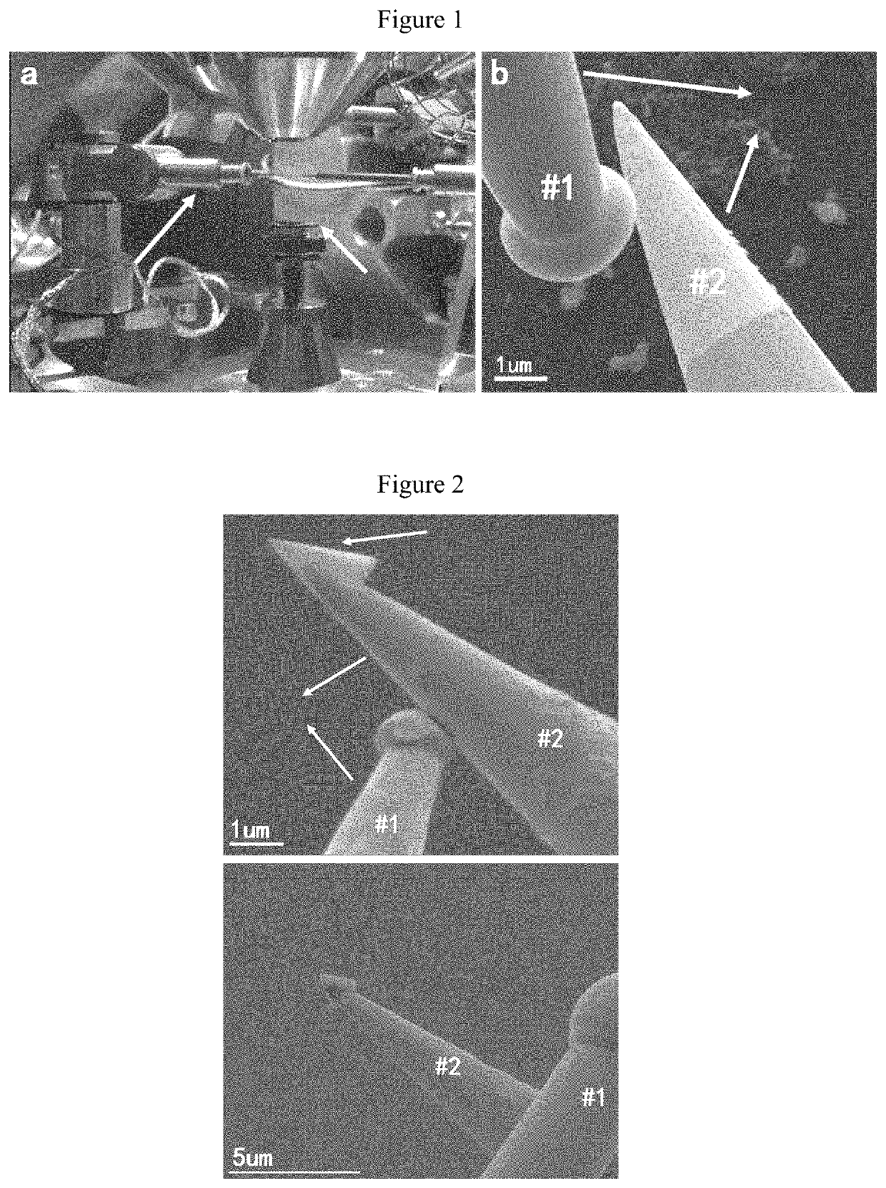
[0051]The conical nano-carbon material was dispersed in the solvent of dichlorobenzene by ultrasonication, and the conical nano-carbon material in the obtained dispersion liquid was dispersed and deposited on the silicon wafer substrate by a spin coater, and then the silicon wafer substrate was installed on the sample stage 3 of a scanning electron microscope (FIG. 1, Panel a). The metal tungsten needle tip (#2) gradually approached and was inserted into the inner space of the conical nano-carbon material under the control of the micromanipulator arm 2, as shown in FIG. 3, Panels a to c. After the metal tungsten needle tip was in physical contact with the inner surface of the conical nano-carbon, the needle tip was moved upward by the micromanipulator arm to separate the conical nano-carbon material from the surface of the substrate.

[0052]FIG. 4, Panels a through e, shows the photographs of the conical nano-carbon material having different cone angles and morphologies adhered to the...

example 2

[0053]The dispersion of the conical nano-carbon material was the same as that in Example 1. In this Example, first, a tungsten needle (#1) was allowed to approach the side wall of the #2 needle tip at the position 10 μm away from the top of the #2 needle tip, and a voltage of 60 V was applied between the #1 tungsten needle and the #2 needle body, so that an arc occurred between the #1 tungsten needle and the #2 needle body, which caused the top of the #1 tungsten needle to melt into a spherical shape.

[0054]The tip of the #2 needle was inserted into the top of the conical nano-carbon material (the length of the generatrix of the cone was about 1 and the apex angle was about) 60° and contacted with the conical nano-carbon material 6, so that the conical nano-carbon material 6 was adhered to the top of the tungsten needle tip.

[0055]Thereafter, the spherical top of the #1 tungsten needle was directly contacted with the outer surface of the conical nano-carbon on the above tungsten needl...

example 3

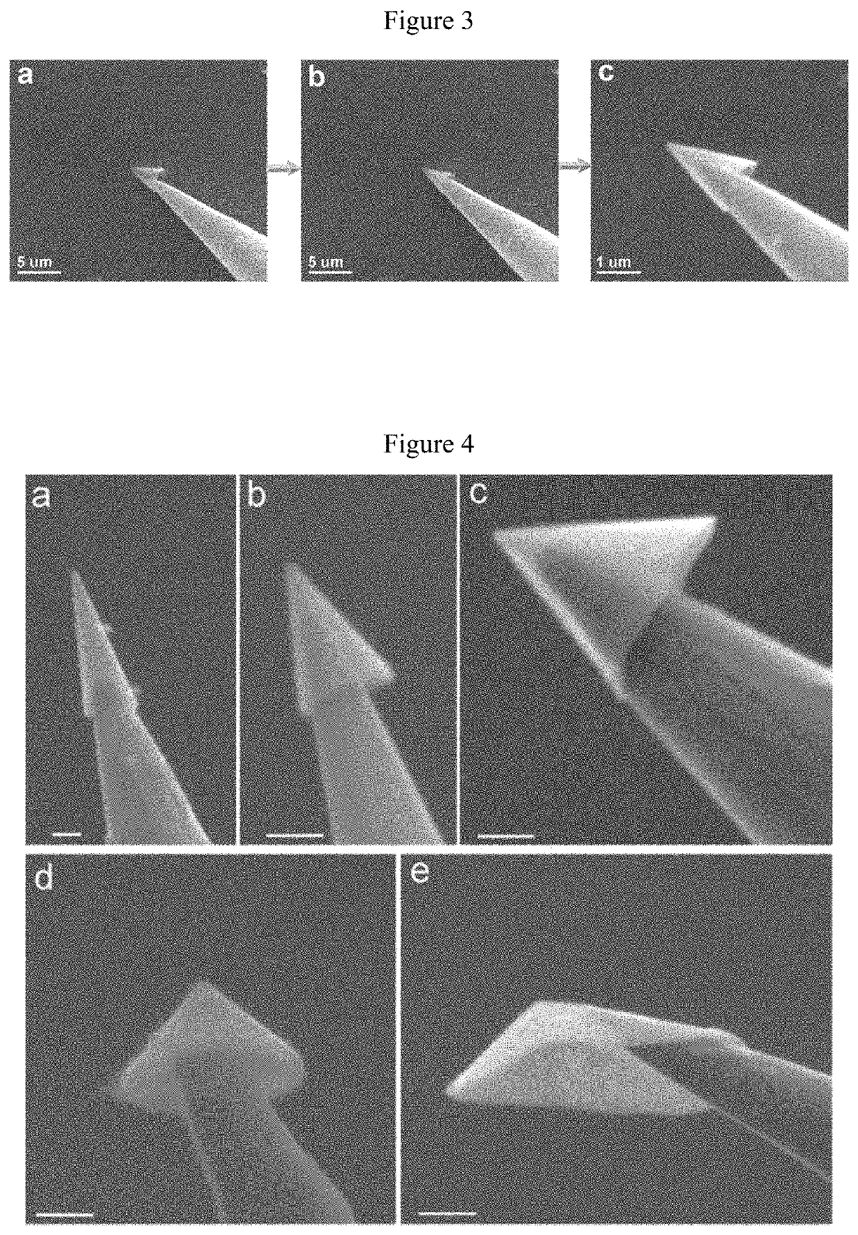
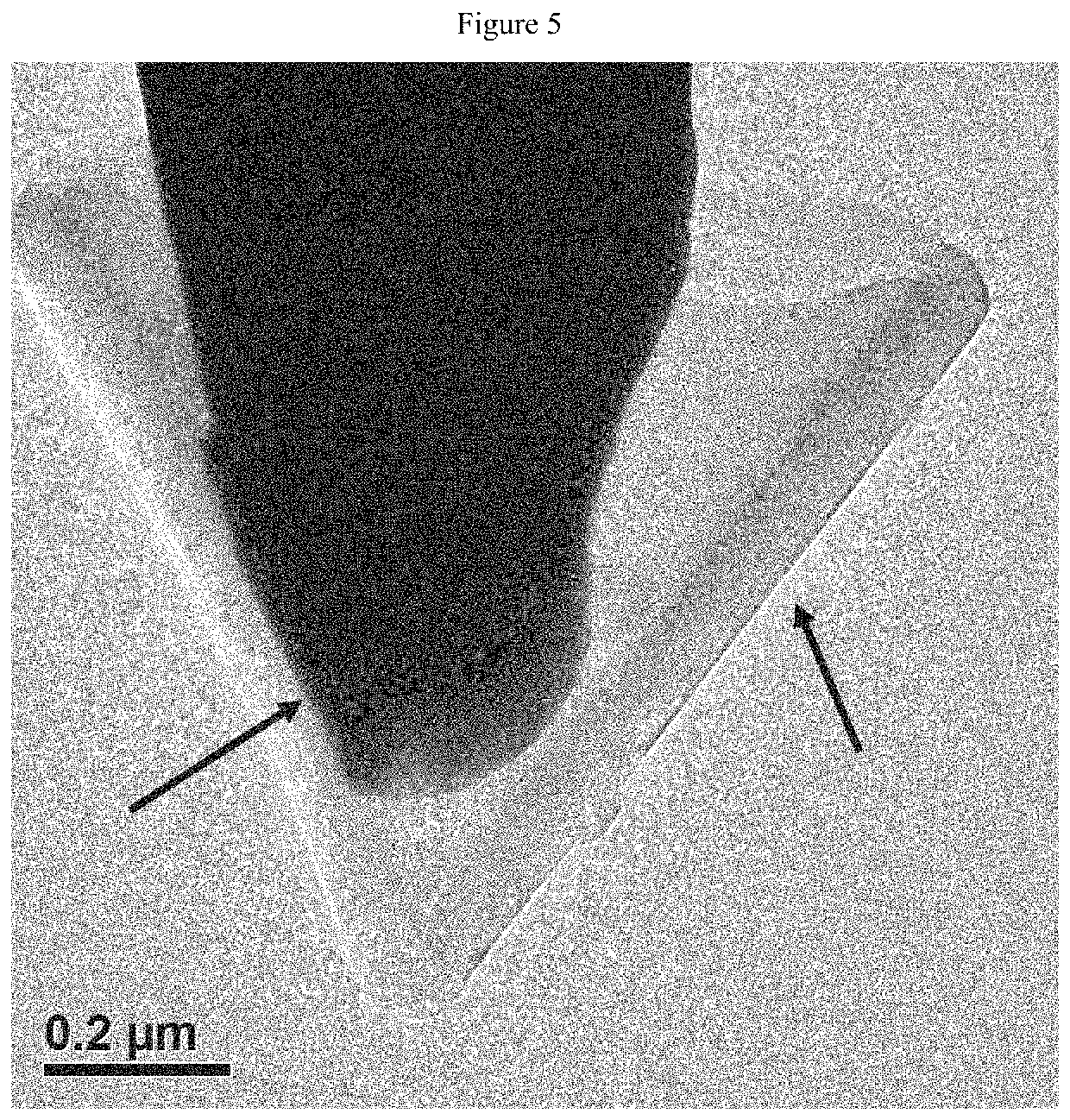
[0056]In this Example, a conical nano-carbon material (the apex angle of the cone was about 40°) was adhered to the top of the tungsten needle tip. Thereafter, the spherical top of the other tungsten needle tip (#1) was brought into contact with the above tungsten needle tip (#2), and the contact position was about 3 μm away from the top of the needle tip #2 (FIG. 2, Panel a). A voltage was applied to the two tungsten needle tips to generate a current of 3 A with a duration of 0.25 ms, resulting in a functionalized needle tip as shown in FIG. 6, Panels a and b. In this Example, the metal tungsten needle tip (#2) was melted in a large area, and the melted metal tungsten automatically entered and filled the inner space of the conical nano-carbon, and the orientation of the conical nano-carbon was matched with the axial direction of the tungsten needle tip. X-ray photoelectron spectroscopy analysis results show that at this high temperature, the melted tungsten reacts with the inner su...


PUM

PropertyMeasurementUnit
lengthaaaaaaaaaa
voltageaaaaaaaaaa
electric currentaaaaaaaaaa

Abstract

Provided is a conical nano-carbon material functionalized needle tip, formed by assembling a nano-carbon material with a material of a needle tip by means of a covalent bond; and the material of the needle tip is a metal selected from one or more of tungsten, iron, cobalt, nickel and titanium. Further provided is a method for preparing the conical nano-carbon material functionalized needle tip. The conical nano-material functionalized needle tip has an outstanding interface formed by metal-carbide covalent bonds, and the orientation of the conical nano-material is matched with the axial direction of the metal needle tip (illustrated in FIG. 6). The proposed preparation method affords a robust interface and avoids the potential pollution to the nano-material caused during the deposition of fixing materials, such as carbon or platinum or the like, in other preparation methods.

Description

CROSS-REFERENCE TO RELATED APPLICATIONS[0001]This application is a national phase entry under 35 U.S.C. § 371 of International Patent Application PCT / CN2016 / 077671, filed Mar. 29, 2016, designating the United States of America and published as International Patent Publication WO 2017 / 140011 A1 on Aug. 24, 2017, which claims the benefit under Article 8 of the Patent Cooperation Treaty to Chinese Patent Application Serial No. 201610091160.0, filed Feb. 18, 2016.TECHNICAL FIELD[0002]The present invention belongs to the field of functionalization of metal materials, and particularly relates to a needle tip modified by a nano-carbon material and a preparation method thereof.BACKGROUND ART[0003]With the rapid development of nano-materials and nanotechnology, researchers have prepared a number of new nano-material functionalized needle tips, mainly including carbon nanotube tips, and needle tips modified by one-dimensional / quasi-one-dimensional nano-materials such as nanowires. Nano-materi...

Claims


Application Information

Patent Timeline
Patent Type & Authority Patents(United States)
IPC IPC(8): G01R1/067B81B1/00G01R3/00G01Q70/12G01Q30/02B82Y30/00G01Q70/18G01Q70/10B81C1/00
CPCG01R1/06744G01R1/0675B81C1/00G01Q70/18G01R1/06755B82Y30/00G01R3/00G01Q70/12B81B1/00G01R1/06738G01Q70/10G01Q30/02B81B1/008B81C1/0038
Inventor XU, JIANXUNZHAO, YULIANG
Owner THE NAT CENT FOR NANOSCI & TECH NCNST OF CHINA
Why Eureka
Try Eureka