Radio-frequency module and communication apparatus

a radio-frequency module and communication apparatus technology, applied in the direction of printed circuit aspects, cross-talk/noise/interference reduction, association of printed circuit non-printed electric components, etc., can solve the problem of preventing the securement of sufficient ground potential, reducing the distance between wiring lines and electrodes in the module substrate, and generating parasitic inductance and parasitic capacitance, etc. problem, to achieve the effect of suppressing the degradation of radio-frequency transmission characteristic and the radio-frequency transmission characteristic characteristi

Active Publication Date: 2020-12-22
MURATA MFG CO LTD
View PDF26 Cites 4 Cited by
  • Summary
  • Abstract
  • Description
  • Claims
  • Application Information

AI Technical Summary

Benefits of technology

[0006]Accordingly, the present disclosure has been made to solve the above-described issue, and an object thereof is to provide an RF module in which the layout of wiring lines and ground electrodes are optimized to suppress degradation in an RF transmission characteristic and a communication apparatus.
[0028]According to the radio-frequency module or communication apparatus according to the present disclosure, the layout of wiring lines and ground electrodes are optimized, and thus degradation in the radio-frequency transmission characteristic can be suppressed.

Problems solved by technology

As the miniaturization and integration of RF modules advances, the distances between wiring lines and electrodes in a module substrate decrease, resulting in generation of a parasitic inductance and parasitic capacitance.
The miniaturization and integration limits the number of ground terminals for external connection disposed on the module substrate, which prevents a sufficient ground potential from being secured.
This causes an issue of degradation in the RF transmission characteristic of the RF module.
Furthermore, a parasitic inductance and parasitic capacitance interposed between the ground electrode in the filter element and an external-connection ground terminal disposed on the module substrate may change the attenuation pole in an unintended direction and may degrade an attenuation characteristic.

Method used


Image

  • Radio-frequency module and communication apparatus
  • Radio-frequency module and communication apparatus
  • Radio-frequency module and communication apparatus

Examples


first embodiment

(First Embodiment)

[1.1 Configuration of Communication Apparatus]

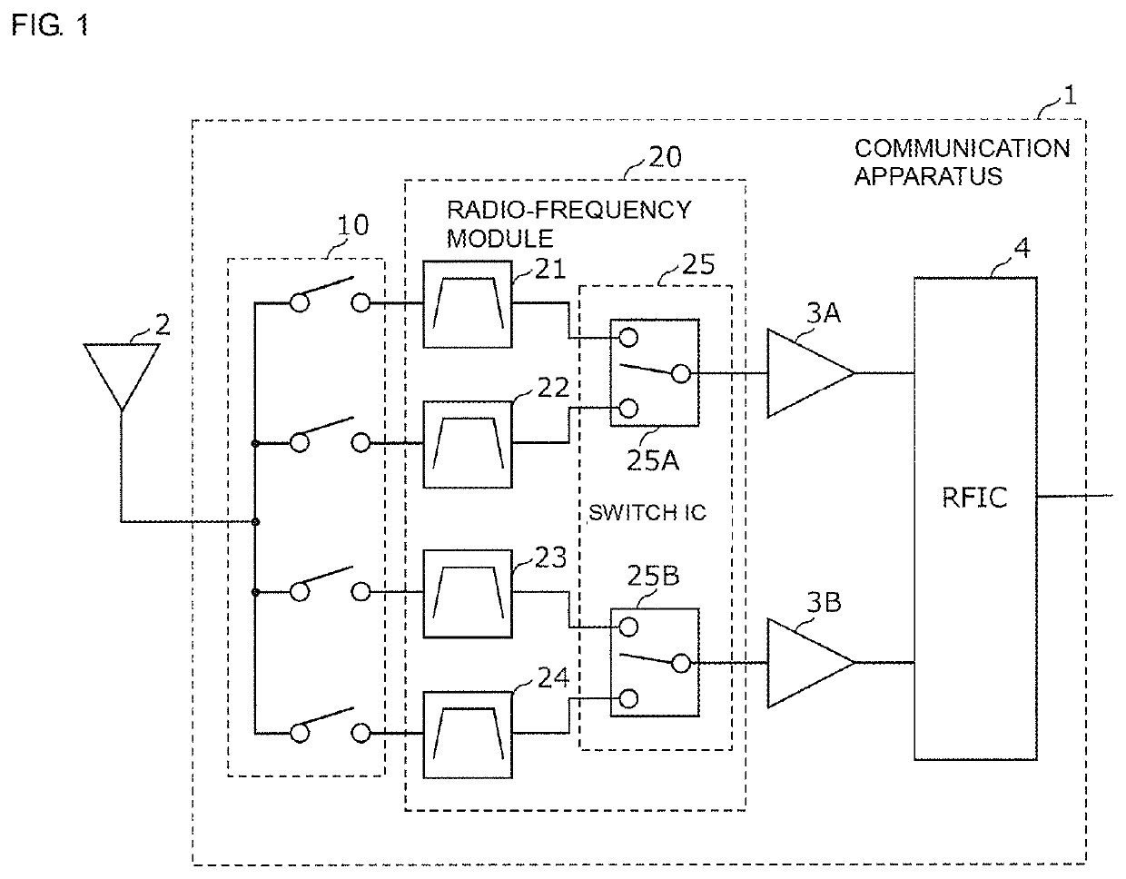
[0042]FIG. 1 is a functional block configuration diagram of a communication apparatus 1 according to a first embodiment. FIG. 1 illustrates the communication apparatus 1 and an antenna element 2. The communication apparatus 1 includes a switch group 10, a radio-frequency (RF) module 20, receiving amplifier circuits 3A and 3B, and an RF signal processing circuit (RFIC) 4. The switch group 10 and the RF module 20 are disposed, for example, at a front-end portion of a multi-mode / multi-band cellular phone.

[0043]The switch group 10 is constituted by one or more switches (in the present embodiment, four SPST switches) each of which connects the antenna element 2 and a signal path corresponding to a predetermined band to each other in response to a control signal from a control unit (not illustrated). The number of signal paths connected to the antenna element 2 at the same time is not limited to one, but may be two or more. I...

second embodiment

(Second Embodiment)

[0105]In the first embodiment, a description has been given of the arrangement of ground electrodes of a filter element mounted on the front surface of a module substrate. In the present embodiment, a description will be given of the arrangement of ground electrodes of an IC chip mounted on a module substrate.

[2.1 Configuration of RF Module]

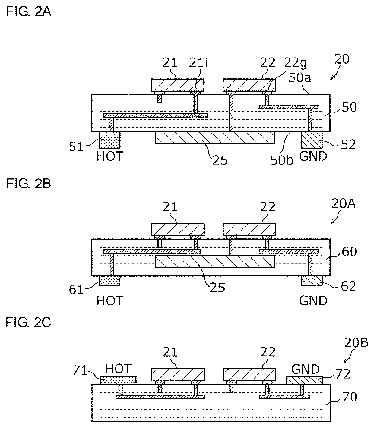
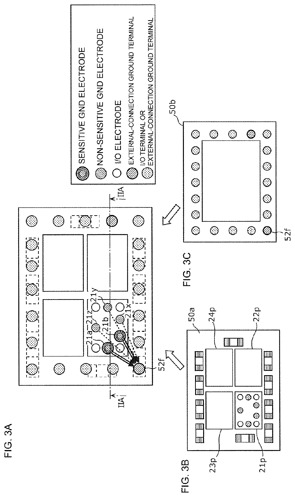
[0106]FIG. 7 is a plan view illustrating the arrangement relationship among electrodes and terminals of the RF module according to the second embodiment. The RF module according to the present embodiment has the cross-sectional configuration illustrated in FIG. 2A. FIG. 7 is a perspective plan view illustrating the arrangement and connection relationships among the individual terminals disposed in an outer peripheral portion of the rear surface of the module substrate 50 and the individual electrodes disposed (in a partial region) in the switch IC 25.

[0107]FIG. 7 illustrates external-connection ground terminals 52b, 52d, and 52...


PUM


Abstract

A radio-frequency module (20) includes a module substrate (50) and a filter (21). The filter (21) has a sensitive GND electrode and a non-sensitive GND electrode that are connected to an external-connection ground terminal of the module substrate (50), and parallel-arm resonators. An inductance component generated by the sensitive GND electrode shifts, by a first shift amount, an attenuation pole that corresponds to a parallel-arm resonator and that is formed near a pass band. An inductance component generated by the non-sensitive GND electrode shifts, by a second shift amount, an attenuation pole that corresponds to a parallel-arm resonator and that is formed near the pass band. The first shift amount is larger than the second shift amount, and the distance between the sensitive GND electrode and the external-connection ground terminal is smaller than the distance between the non-sensitive GND electrode and the external-connection ground terminal.

Description

[0001]This is a continuation of International Application No. PCT / JP2017 / 045403 filed on Dec. 18, 2017 which claims priority from Japanese Patent Application No. 2016-254496 filed on Dec. 27, 2016. The contents of these applications are incorporated herein by reference in their entireties.BACKGROUND OF THE DISCLOSUREField of the Disclosure[0002]The present disclosure relates to a radio-frequency module and a communication apparatus.Description of the Related Art[0003]In recent years, to cope with the miniaturization and higher integration of radio-frequency (RF) front-end circuits, RF modules including a filter circuit, a switch circuit, an amplifier circuit, and the like that are integrated together have been developed. Patent Document 1 discloses an RF switch module in which an RF switch for switching between a transmission path and a reception path is integrated with a surface acoustic wave (SAW) filter disposed on the reception path.[0004]Patent Document 1: Japanese Unexamined P...

Claims


Application Information

Patent Timeline
Patent Type & Authority Patents(United States)
IPC IPC(8): H04B1/04H03H9/54H03H9/56H05K1/02H05K1/18H03H9/25H04B1/00H03H9/13H04B1/52H03H9/205H03H9/64H04B1/18
CPCH03H9/13H04B1/00H03H9/542H05K1/181H05K1/0216H05K1/0243H03H9/64H03H9/25H03H9/568H04B1/0475H03H9/205H05K2201/10083H04B1/18H04B1/52H05K2201/1006H03H9/6483H03H9/02952H03H9/0552H03H9/0557H03H9/72H04B1/0057H05K1/0233H05K1/185H05K2201/09618
Inventor NISHIKAWA, HIROSHI
Owner MURATA MFG CO LTD
Why Eureka
Try Eureka