Techniques for laser ablation/scribing of coatings in pre- and post-laminated assemblies, and/or associated methods
a technology of laser ablation and coating, which is applied in the direction of parallel plane units, manufacturing tools, instruments, etc., can solve the problems of ionized moisture ingress, deterioration of coating, and gradual corrosion from the edge to the center of the lite, so as to increase the electrochemical corrosion resistance of the coating
- Summary
- Abstract
- Description
- Claims
- Application Information
AI Technical Summary
Benefits of technology
Problems solved by technology
Method used
Image

Examples
example 1
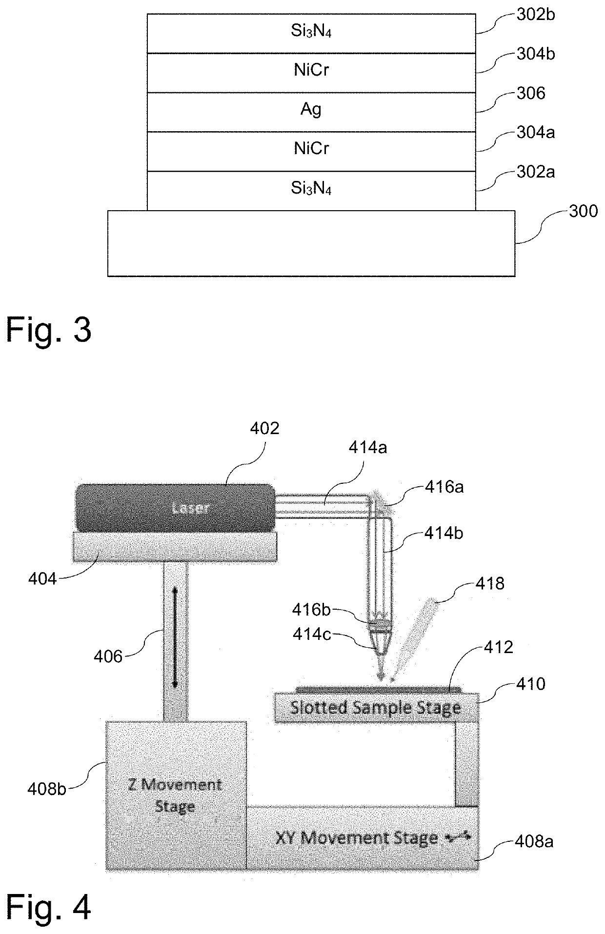
[0045]
PreferredMore PreferredExampleThicknessThicknessThicknessLayer(nm)(nm)(nm)Si3N4 (302b)385-525405-505455NiCr (304b)20-3022-2825Ag (306) 95-135100-130115NiCr (304a)30-5035-4540Si3N4 (302a)110-150115-145130Glass (300)N / AN / AN / A
example 2
[0046]
PreferredMore PreferredExampleThicknessThicknessThicknessLayer(nm)(nm)(nm)Si3N4 (302b)435-595460-570515NiCr (304b)25-3527-3330Ag (306)105-145110-140125NiCr (304a)20-3022-2825Si3N4 (302a)235-325250-310280Glass (300)N / AN / AN / A
example 3
[0047]
PreferredMore PreferredExampleThicknessThicknessThicknessLayer(nm)(nm)(nm)Si3N4 (302b)360-490380-470425NiCr (304b)30-5035-4540Ag (306)55-7558-7265NiCr (304a)35-5540-5045Si3N4 (302a)260-360280-340310Glass (300)N / AN / AN / A
[0048]Considering the three examples above, Example 3 has the thickness undercoat (e.g., the layer comprising Si3N4 302a), and it seemingly has the greatest propensity for corrosion. Example 1 has the thinnest undercoat (e.g., the layer comprising Si3N4 302a), and it seemingly smallest propensity for corrosion. There are, however, additional or alternative hypotheses as to why these phenomena are encountered. First, it is possible that the undercoat (e.g., the layer comprising Si3N4 302a) in Example 3 may be rougher than the corresponding layers in the other coatings, potentially caused by its greater thickness, and potentially leading to poorer interfacial adhesion and in turn leading to corrosion more easily. Second, there may be greater tensile strength in the...
PUM
| Property | Measurement | Unit |
|---|---|---|
| width | aaaaa | aaaaa |
| thicknesses | aaaaa | aaaaa |
| transparent | aaaaa | aaaaa |
Abstract
Description
Claims
Application Information