Universal vehicle with improved stability for safe operation in air, water and terrain environments

a technology of safe operation and stability, applied in the field of vehicle transportation industry, can solve the problems of limited control capabilities of these systems, affecting the safety of the aircraft, and the helicopter system is generally only halfway efficient in the airplane system, so as to improve the stability of the vehicle and ensure the safe operation. safe transition, the effect of improving the stability

Active Publication Date: 2021-06-15
UNIV OF MARYLAND
View PDF24 Cites 0 Cited by
  • Summary
  • Abstract
  • Description
  • Claims
  • Application Information

AI Technical Summary

Benefits of technology

[0022]It is therefore an object of the present invention to provide an advanced aviation vehicle with an enhanced flight envelope by introducing effective V / STOL capability of uncompromised and balanced operation in, and safe transitioning between the airplane and the helicopter modes of operation.
[0023]It is, another object of the present invention to provide a robust aerial vehicle capable of short take-off, short landing, vertical take-off, and / or vertical landing, that is compact, easy to manufacture, capable of both sustained vertical and horizontal flight, hovering, efficiently and safely transitioning in any sequence between vertical and horizontal flight regimes, launchability from either stationary and / or moving platform, and that is indifferent to launching / landing zone surface qualities and / or terrain types utilized during take-off and / or landing.
[0024]It is a further object of the present invention to provide the aerial vehicle capable of V / STOL which is based on merging the lifting body concept with thrust vectoring while solving the tilt wing and tilt rotor deficiencies during the flight mode transition, attained substantially in two manners: (a) by harvesting the benefits of the lifting body to create lift at high angles of attack and achieve favorable stall performance, while maximizing lift area to provide useful lift for the vehicle, and (b) by alleviating the requirements for the propulsion system based on the available lift of the lifting body during transition, even at high angles. As a result, the subject system is capable of achieving sustained vertical flight and safe transition with either smaller propeller systems or large diameter blade systems.

Problems solved by technology

These aerial vehicles usually are not capable of using aerodynamic lift forces during transition between the take-off and landing flight regimes.
Another disadvantage of the existing V / STOL platform is that tilt rotor and tilt wing concepts are generally only halfway efficient in a helicopter system and halfway efficient in an airplane system.
However, the design of these aircraft systems permit neither the Vertical Take-off and Landing (VTOL), nor the vertical flight or the hovering flight.
Moreover, the control capabilities of these systems are limited only to manipulating the airflow for roll moment control, and controlling pitch and yaw only by actuation of trailing edge surfaces.
Additional limitations of the prior art systems operation are due to mounting the on-board propulsion system in a rigid (fixed) fashion.
These vehicles have shortfalls that are mainly derived from the compromise between the aerodynamic based flight (the airplane mode of flight) and powered lift (the helicopter mode of flight).
In essence, the overall efficiencies for these flight modes of operation are polar opposites, and have inherently contradicting mechanisms of achieving flight.
However, the large blades, when tilted to the airplane mode of flight, generate a large drag penalty even though they are attempting to move the entire vehicle forward.
Additionally, the large blades needed for hovering have large impact on the vehicle's ground clearance, available wing span, structural stability, overall mechanical complexity and safety.
Conversely, a small propeller, while best suited for the airplane mode of flight, will not efficiently move the required volume of air to offset the vehicle's weight by means of a powered lift alone.
Thus, the existing tilt wing and tilt rotor vehicles do not employ small propellers.
While the optimization for the end point flight modes of operation, i.e., the airplane mode and the helicopter mode, is challenging enough, the transition between the two flight modes is more perilous.
At any interim angle during the tilt evolution between 90 degrees (in the helicopter mode) and ˜0 degrees (in the airplane mode), the hand-off between the powered lift and aerodynamic lift (and vice-versa) often generates aeronautical problems.
Furthermore, the ground speed is insufficient for the appreciable aerodynamic lift generation from the limited available wing area (if the available wing area is not at stall angles of attack).
The required twist on the propeller to make the airplane mode efficient and achieve higher speed horizontal flight is prone during the helicopter mode of operation to blade stall.
The irreversible stall condition implies that transitioning to vertical flight or landing vertically is extremely dangerous should a descent rate consistent with generating the sudden loss of lift be present.
Thus, the mismatch of the lift generation from one rotor to the other causes an immediate roll moment which may cause catastrophic results.
In the present technology era, while the military utilizes the tilt rotor V-22 Osprey, such poses many aerodynamic problems.
In various ways both the Pogo and XFV-1, while also suffering from flight transition difficulties (especially after high speed horizontal flight back to stationary vertical orientation), mechanical complexity and safety concerns, had an additional flaw in that wind gusts played havoc during vertical operation.
Even while at rest, the narrow footprint of the landing gear system and high vehicle CG (center of gravity) made tailsitter vehicles susceptible to tip-over in the presence of high wind.

Method used


Image

  • Universal vehicle with improved stability for safe operation in air, water and terrain environments
  • Universal vehicle with improved stability for safe operation in air, water and terrain environments
  • Universal vehicle with improved stability for safe operation in air, water and terrain environments

Examples


Embodiment Construction

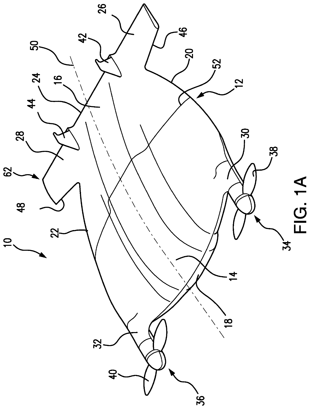
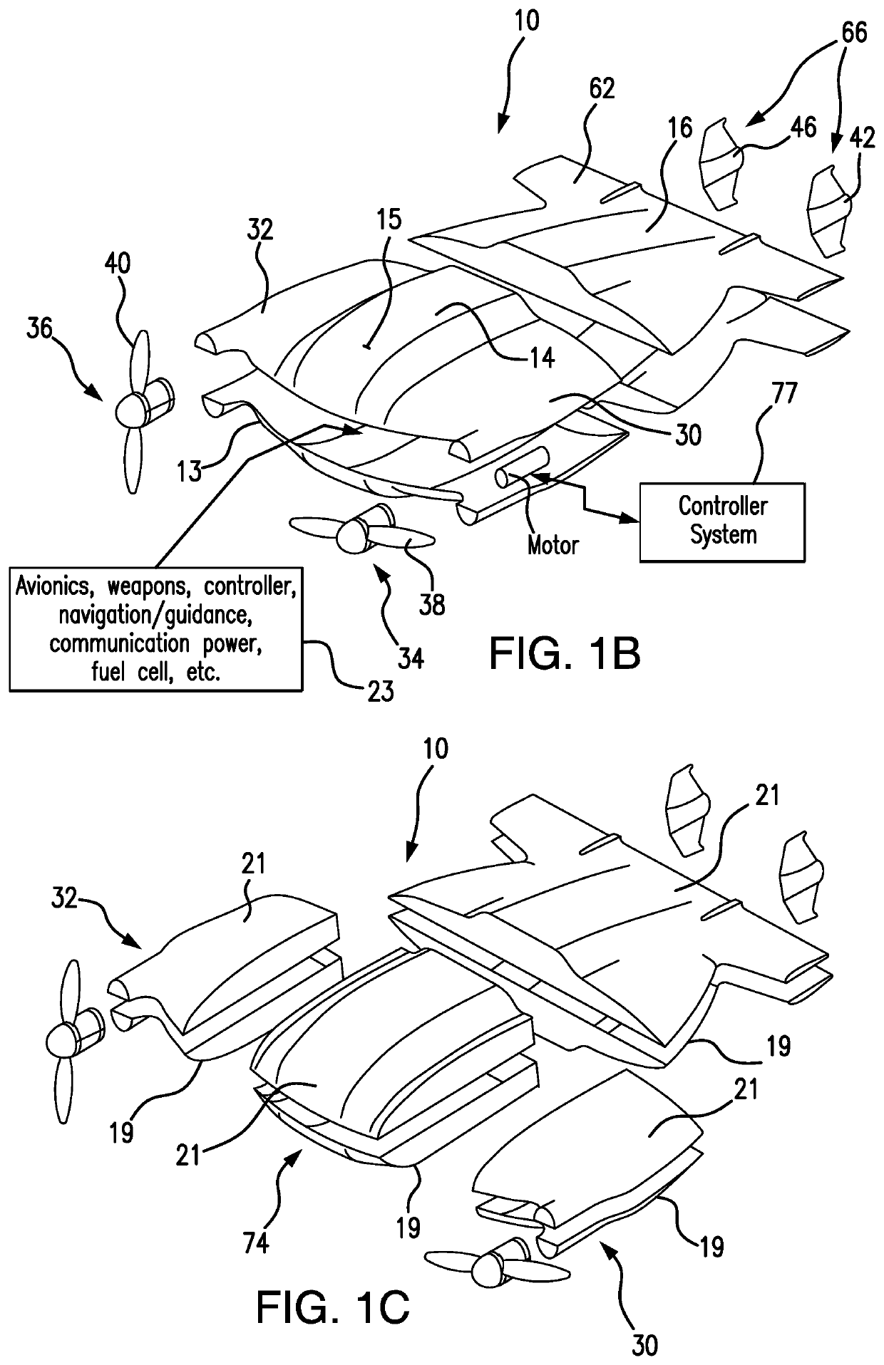
[0103]In the present aircraft design, the effectiveness and versatility of the vehicle results from the combined integration of the vehicle's sub-systems and their cross functionality. The concept underlying the design and operation of the subject system is not limited to the use of sub-systems with exclusively dedicated functions, but rather capable of multiple function systems. For example, some of the proposed embodiments combine the thrust vectoring nacelles with the landing gear and / or payload compartment. The vehicle body functions as both a primary lift generation and avionics / payload compartmentalization, the trailing edge of the lifting body, and horizontal and vertical stabilizers, and / or rear vehicle body and also function as a landing apparatus.

[0104]The aircraft of the present invention, when used as an Unmanned Aerial System, may be used to meet various end-user needs such as, but not limited to, security monitoring, crisis mitigation, disaster relief, scientific sensi...


PUM


Abstract

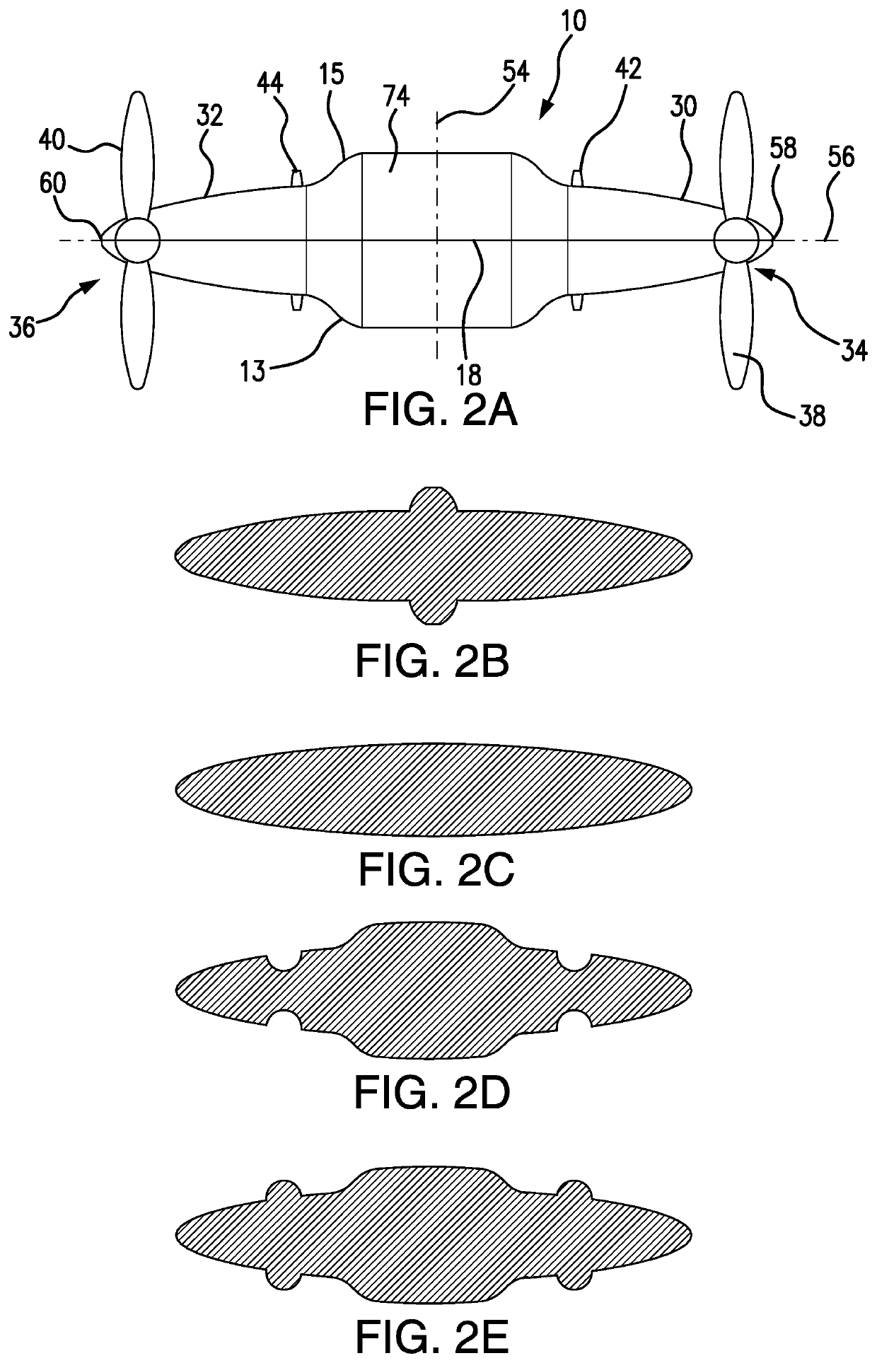
The universal vehicle system is designed with a lifting body which is composed of a plurality of interconnected modules which are configured to form an aerodynamically viable contour of the lifting body which including a front central module, a rear module, and thrust vectoring modules displaceably connected to the front central module and operatively coupled to respective propulsive mechanisms. The thrust vectoring modules are controlled for dynamical displacement relative to the lifting body (in tilting and / or translating fashion) to direct and actuate the propulsive mechanism(s) as needed for safe and stable operation in various modes of operation and transitioning therebetween in air, water and terrain environments.

Description

REFERENCE TO THE RELATED PATENT APPLICATION(S)[0001]The Utility patent application is a National Stage Application of PCT / US2016 / 049429 filed on 30 Aug. 2016 and is based on a Provisional Patent Application No. 62 / 212,312 filed on 31 Aug. 2015.FIELD OF THE INVENTION[0002]The present invention is directed to the vehicle transportation industry, and particularly, to unmanned and manned aerial vehicles dynamically adaptable for travel in aerial, marine, and surface environments in an autonomous and remotely piloted control regime.[0003]The subject invention is further directed to a vehicle with improved stability and safety of operation in either air, water, or terrain environment provided with a dynamically controlled mechanism for real-time control either of pitch, roll, and yaw moments by dynamically manipulating (passively and / or actively) the vehicles' characteristics which may include either of the following: center of thrust, moment arm of center of thrust related to the center ...

Claims


Application Information

Patent Timeline
Patent Type & Authority Patents(United States)
IPC IPC(8): B64C37/00B64C15/12B64C29/00B64C39/02B64C39/10B64C17/02B64C5/02B64C11/46B64C19/00B64C29/02B64D29/00
CPCB64C37/00B64C5/02B64C11/46B64C15/12B64C17/02B64C19/00B64C29/0033B64C29/02B64C39/024B64C39/10B64C2201/028B64C2201/088B64C2201/205B64C2201/208B64C2211/00B64D29/00B64U10/25B64U70/80B64U80/84B64U80/86
Inventor VALENTE, EVANDRO GURGEL DO AMARALWERELEY, NORMAN M.VALENTE, EDUARDO GURGEL DO AMARAL
Owner UNIV OF MARYLAND
Why Eureka
Try Eureka