Solar desalination system

a desalination system and solar energy technology, applied in the direction of contaminated groundwater/leachate treatment, mechanical equipment, machines/engines, etc., can solve the problems of contaminated groundwater resources, affecting the operation of the system, and forming membrane fouling films, etc., to achieve the effect of controlling corrosion, smooth surface, and thinner surfa

Active Publication Date: 2021-08-24
CHOI PETER B
View PDF5 Cites 0 Cited by
  • Summary
  • Abstract
  • Description
  • Claims
  • Application Information

AI Technical Summary

Benefits of technology

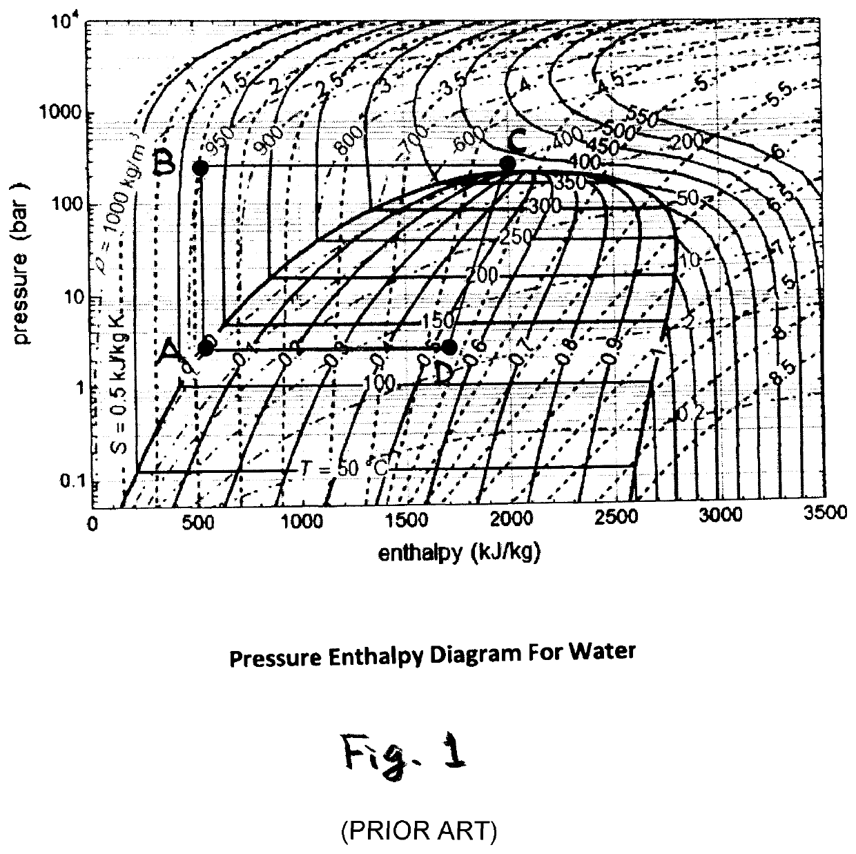
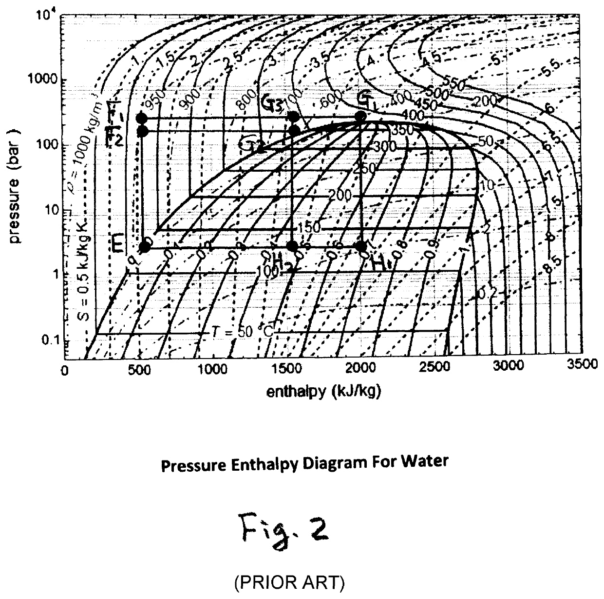
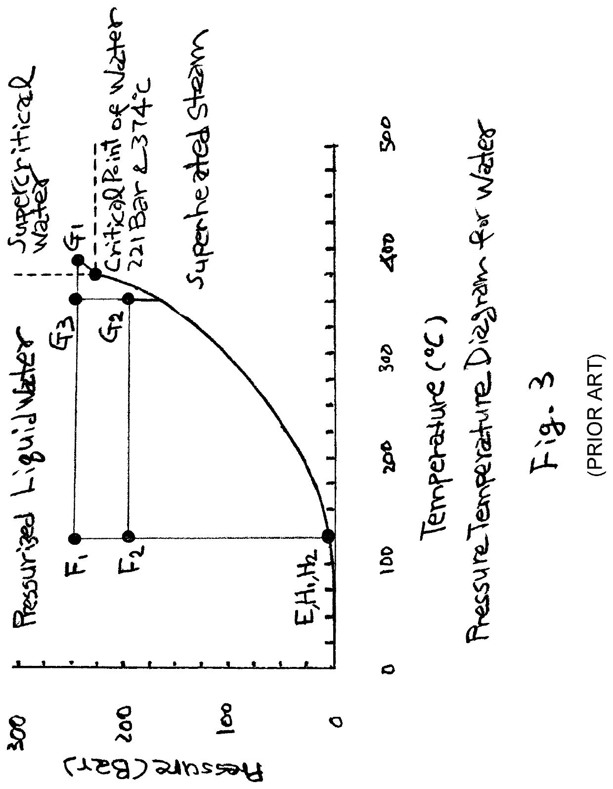
[0021]When the SPF is generated, the water is pressurized and heated at the optimum pressure and temperature between around 20 bar and 300 bar in pressure and between around 190° C. and 400° C. in temperature, where the required steam quality can be attained when the SPF undergoes an isenthalpic expansion into the vapor-liquid region to the lower operating pressures for the desalination unit. The optimum means the lowest in cost while achieving the goal safely. Therefore, the steam quality at the operating pressure of the desalination process determines the pressure and temperature for the SPF to be generated at in the CSP unit. For example, in the case when a steam quality of 32% is needed at 30 bar in the process, the SPF can be heated to 337° C. at 190 bar, which is in the region of pressurized liquid water and will produce 32% steam when its pressure is reduced to 30 bar by an isenthalpic expansion. In the case when a steam quality of 52% is needed at 30 bar, on the other hand, the SPF can be heated to 380° C. at 250 bar, which is in the region of supercritical water and will produce 52% steam when its pressure is reduced to 30 bar by an isenthalpic expansion. At this pressure, an isentropic expander for electricity generation can be operated using this steam. Also, a steam jet ejector can be operated using this steam as motive steam for recycling the water vapor from the desalination unit. Once produced at the required pressure and temperature, the SPF is stored in the storage tanks for use in the night.
[0023]An advantage of generating the SPF in single-phase is that the once-through generation can avoid the phase segregation that would occur when liquid water vaporizes into steam in the two phase region below the critical pressure. However, when the water is heated in single-phase through the pressurized liquid water phase region and then through the supercritical water phase region, the SPF passes through the single-phase regions with no segregation of phases that would otherwise cause uneven heat transfer.
[0029]By using the SPF as a source of the motive steam in a pressure range from the critical pressure of water to 2 bar (absolute), a MED-TVC unit can operate at higher performance ratio (PR) with a steam jet ejector. The MED-TVC can recycle the heat of vaporization contained in the water vapor generated in the last effect of the desalination unit. The goal of this invention is to recycle 20% to 40% of this water vapor. Owing to the heat recovery by the water vapor recycling through the steam jet ejector, a MED unit having a performance ratio (PR) of 9 will achieve a PR of about 11 to 15 by addition of a steam jet ejector with the water vapor recycling of 20% to 40%, respectively. The water vapor recycling enables reduction of the capacity of the CSP and TES units as much as the energy saved by the water vapor recycling while reducing the price of the product fresh water by 14% to 28%, respectively. For a TVC unit, on the other hand, the condensate of SPF is in better quality than the distillate. This advantage makes the design of the TVC unit so simple with no steam transformer needed. By combining with the CSP unit and the TES of SPF, it can produce fresh water from the high-salt groundwater at reasonable investment and O&M costs. The TVC can reduce the capacity of the CSP unit and SPF storage system as much as the thermal energy being recovered from the streams of the exit brine concentrate and the condensate of the discharge steam mixture based on the new steam prices derived from the solar energy. Since a TVC unit can produce fresh water up to 3000 m3 / day, which can support about 3000 families, it will provide invaluable opportunities to supply drinking water from the high-salt groundwater in remote arid areas.
[0030]The comparison shows that the SPF is the most competitive as a TES medium and HTF with LFR as a CSP unit for this application. The SPF storage system comprises a plurality of storage tanks. This SPF storage stores the SPF in the fullest extent and discharges in full, while the stored thermal energy can be recovered in the form of electricity and the low pressure steam for use either as heating medium or motive steam for steam jet ejectors in desalination units. It can also generate high pressure steam as a motive steam for steam jet ejectors, and steam condensate as a heating medium. The price of solar salt is about $2,000 / m3 and of thermal oil $25,000 / m3, while that of water lower than $5 / m3. Accordingly, the SPF is more advantageous in this application compared to the thermal oil and solar salt. The low pressure steam from the electric generator and the steam condensate are used as a heating medium until the condensate temperature reaches 130° C. for desalination unit. The low pressure steam above 2 bar (absolute) can be also used as motive steam for steam jet ejectors in MED-TVC and TVC units. Since this SPF storage allows the desalination unit to recover thermal energy from the steam condensate, its thermal recovery efficiency is much higher than High Temperature Water Systems which have an average volumetric heat content of about 200 MJ / m3 with a temperature differential of 50° C. for sensible heat transfer or the Steam Accumulators which recover flash steam from the stagnant pool of hot water at pressures up to 45 bar with a thermal storage capacity of 50 minutes. The SPF makes the storage system the most competitive in overall investment cost.

Problems solved by technology

Desalination of high-salt groundwater requires thermal desalination rather than membrane desalination because the latter does not work well due to clogging on the membrane surfaces by the film formed with organic and inorganic components in the high-salt water.
Recently, rapid pace of agricultural contamination, industrialization, and urbanization has resulted in the exploitation and contamination of groundwater resources.
However, they tend to form membrane fouling films being caused by dissolved inorganic (BaSO4, CaSO4, and CaCO3) or organic (humic acids) compounds, collides (suspended particles), bacteria, or suspended solids.
Also, they caused brine disposal problems due to the limited recovery of water.
As for the MFD-TVC unit, it has not been commercially used in the desalination industry.
Therefore, all four systems are capable of generating solar energy as a heat source for desalination unit for the required temperature level of around 130° C. For a desalination unit to operate during the night, however, no cheap thermal storage is available at the present time to produce fresh water in combination with the CSP units.
In addition, the systems usually require large storage volume due to the low volumetric heat content.
The major bottleneck in this approach is that the cost of the storage vessels is too expensive to justify with the amount of utilizable thermal energy by using this system.
In summary, water and steam have shown poor performance as a TES medium so far, even though they have been used as an excellent HTF throughout the human history.
In this case, it requires large heat transfer area causing investment cost to increase.
This could be due to the fact that PT requires flexible joints owing to its tracking system design causing difficulties for operation above supercritical pressure and temperature of water.
The SPT is however very expensive option among the CSP technologies.
For PD, with the current designs available, the working temperature is too high and also thermal capacity too low for production of fresh water at high production rates.
Since no liquid phase exists, the surfaces contacting the supercritical steam cannot be cleaned with liquid water.
The possible deposits will cause corrosion.
However, supercritical steam is rarely generated in commercial CSP units, even though it has been produced by once-through vaporization in coal-fired boilers.

Method used


Image

  • Solar desalination system
  • Solar desalination system
  • Solar desalination system

Examples


first embodiment

[0051]In a first embodiment, the schematic diagram of the solar desalination system 500 with isentropic expansion of SPF is shown in FIG. 5. In the daytime, the condensate water of the SPF is collected in condensate tank 505 at 130° C. and 2.7 bar, and then pumped to the pressure of 250 bar by pump 506. The pump discharge condensate water 551 is then heated to the temperature of 380° C. by a CSP unit 502 for stream 552. The SPF at 380° C. and 250 bar is used to run an expander 503 generating electricity and to operate the desalination unit 504. The condensate water of the SPF after desalination unit collects in condensate tank 505.

[0052]At the same time, the SPF at 380° C. and 250 bar with a volumetric heat content of 626.3 MJ / m3 is stored in SPF storage tank 501. For charging, valve 507 and valve 508 are opened with valve 509 and valve 510 closed. Valve 510 is opened when steam condensate is removed from the storage tank 501 and sent to condensate flash tank 516. Flash steam 563 an...

second embodiment

[0057]In a second embodiment, the schematic diagram of solar desalination system 600 with isenthalpic expansion of SPF is shown in FIG. 6. The difference between FIG. 5 and FIG. 6 is that the isentropic expander 503 is changed to an isenthalpic expanding valve 614 in FIG. 6. The components having reference numerals with the identical last two digits do the same function, respectively, as those in FIG. 5. In the daytime, the condensate water of the SPF is collected in condensate tank 605 at 130° C. and 2.7 bar, and then pumped to the pressure of 250 bar by pump 606. The pump discharge condensate water 651 is then heated to the temperature of 380° C. by a CSP unit 602 for stream 652. The SPF at 380° C. and 250 bar expands to the low pressure at 130° C. and 2.7 bar. The condensate formed during the isenthalpic expansion is sent to the condensate flash tank 616, and then flash steam 663 and steam condensate 664 are sent to the desalination unit for heat recovery. The low pressure steam ...


PUM

PropertyMeasurementUnit
operating temperaturesaaaaaaaaaa
operating pressuresaaaaaaaaaa

Abstract

A single-phase fluid (SPF) storage is introduced for desalination of high-salt water using thermal energy from a concentrated solar power (CSP) unit. The SPF having a specific volumetric enthalpy higher than that of water at critical point in the operating ranges from 20 to 300 bar in pressure and 190 to 400 C in temperature is used as a new type of thermal energy storage (TES) medium and heat transfer fluid (HTF). It produces wet steam of a quality required by the desalination unit generating both steam for utilization of latent heat and condensate for sensible heat when its pressure is reduced to lower operating pressures. With a MED-TVC unit by using the steam as motive steam, the capacity of the CSP unit and SPF storage can be reduced as much as the energy recycled in the desalination unit.

Description

CROSS-REFERENCE TO RELATED APPLICATION[0001]This application claims priority to U.S. Provisional Application No. 62 / 938,993, titled “Solar Desalination System,” filed on Nov. 22, 2019, which is incorporated by reference in its entirety.FIELD OF INVENTION[0002]The present invention is related to the method of production of fresh water by thermal desalination of high-salt groundwater using the thermal energy from a concentrated solar power (CSP) system without stoppage of operation during the night.BACKGROUND OF THE INVENTION[0003]Desalination of high-salt groundwater requires thermal desalination rather than membrane desalination because the latter does not work well due to clogging on the membrane surfaces by the film formed with organic and inorganic components in the high-salt water. Thermal desalination is not affected by the existence of the film forming components as much as the membrane units are. However, thermal desalination units must operate around-the-clock, and this requ...

Claims


Application Information

Patent Timeline
Patent Type & Authority Patents(United States)
IPC IPC(8): C02F1/14C02F1/04C02F1/06F03G6/06C02F103/06
CPCC02F1/14C02F1/041C02F1/06F03G6/067C02F2103/06C02F2201/009F03G2006/061F03G2006/062C02F1/04F03G6/061F03G6/062Y02E10/46Y02A20/124Y02A20/142Y02A20/212
Inventor CHOI, PETER B.
Owner CHOI PETER B
Why Eureka
Try Eureka