
Power module

a power module and power technology, applied in the field of power modules, can solve the problems of power module not meeting the thermal requirements, power module cannot meet the thermal requirements, power module cannot meet the thermal conduction effect between the power module and the casing of the electronic device, etc., to achieve the effect of reducing the power loss of the output inductors, enhancing heat dissipation efficiency, and reducing thermal resistan

Active Publication Date: 2021-10-26
DELTA ELECTRONICS INC
View PDF39 Cites 0 Cited by
  • Summary
  • Abstract
  • Description
  • Claims
  • Application Information

AI Technical Summary

Benefits of technology

The solution effectively reduces power loss and thermal resistance, increases heat dissipation efficiency, and allows for a higher power density by utilizing the magnetic core and electrical conductors to manage heat transfer and mechanical pressure.

Problems solved by technology

Although the dynamic switching performance of the power module of the electronic device is enhanced and the volume of the electronic device is reduced, there are still some drawbacks.
For example, the power module can't meet the thermal requirements because the heat from the power module fails to be conducted to the system board due to the other heat source, for example the central processing unit.
Therefore, the effect of the thermal conduction between the power module and the casing of the electronic device is not satisfied.
Namely, the heat from power module cannot be effectively transferred to the casing of electronic device and dissipated away through the casing of the electronic device.
In case that the force applied to the ball grid arrays of the power module is not uniform, the soldering material is possibly cracked or detached and the product reliability is impaired.
However, the installation space of the output capacitor is restricted.
That is, the power module cannot be equipped with more output capacitors according to the practical requirements.

Method used


Image

  • Power module
  • Power module
  • Power module

Examples


first embodiment

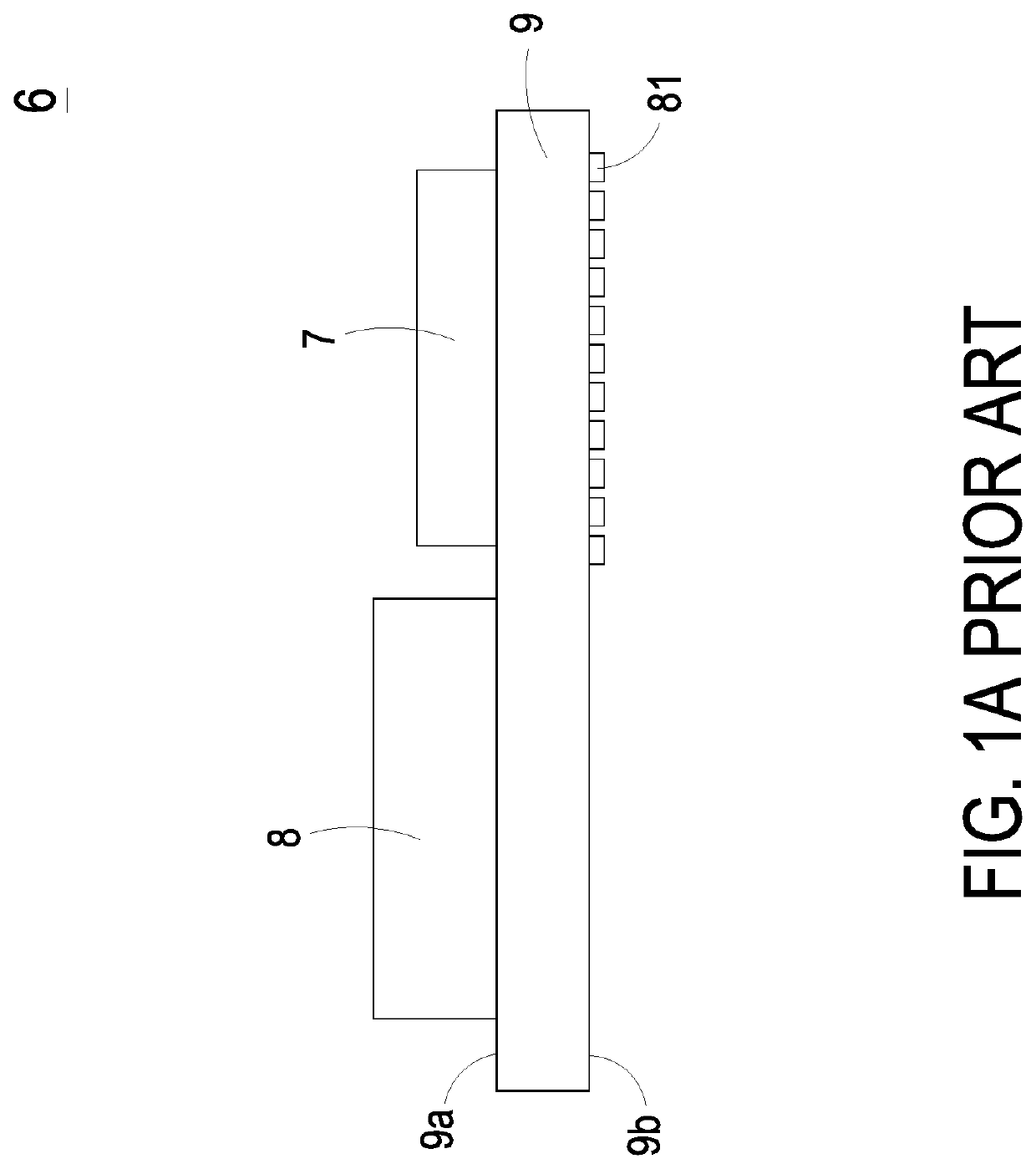
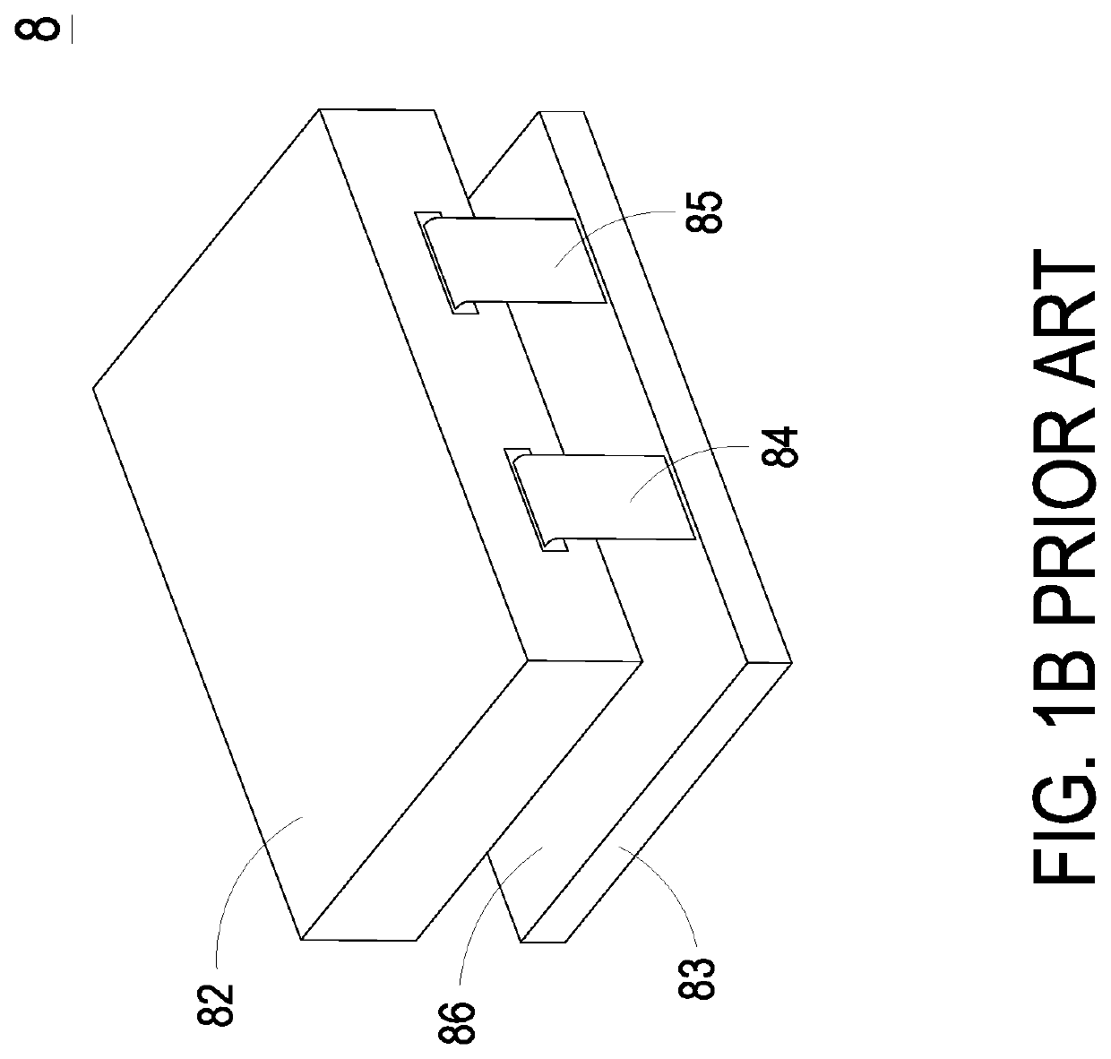
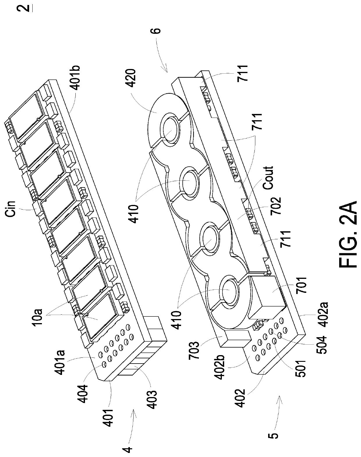
[0031]FIG. 2A is a first schematic exploded view illustrating a power module according to the present disclosure. FIG. 2B is a second schematic exploded view illustrating the power module of FIG. 2A. FIG. 3 is a schematic equivalent circuit diagram illustrating the power module of FIG. 2A. FIG. 4 is a schematic assembled view illustrating the power module of FIG. 2A assembled with a central processing unit and a system board to form an electronic device. As shown in FIGS. 2A, 2B, 3 and 4, the power module 2 is served as a voltage regulator module (VRM) and is applied in an electronic device 1. In this embodiment, the power module 2 is a multi-phase buck converter, for example but not limited to 4-phase buck converter. As the power module 2 is applied in the electronic device 1 to assembly with a central processing unit 7 and a system board 9, the power module 2 and the central processing unit 7 are disposed on the opposite surfaces of the system board 9. The system board 9 has a fir...

second embodiment

[0051]FIG. 7 is a cross-sectional view illustrating a power module according to the present disclosure, wherein the first printed circuit board and the second printed circuit board are omitted from the power module. In some embodiments, the magnetic core portion 420 is rectangle. Corresponding to the magnetic core portion 420, the second electrical conductor 701 and the third electrical conductors 702, 703 are rectangle whose capability of enduring mechanical pressure is not good as wave-shaped. The other structure features and functions of the magnetic core portion 420 and the electrical conductors 701 to 703 as shown in FIG. 7 are similar to the magnetic core portion 420 and the electrical conductors 701 to 703 as shown in FIG. 6, and are not redundantly described therein. It is noted that the shapes of the magnetic core portion 420 and the electrical conductors 701 to 703 are not limited to the above embodiment, and can be varied according to the practical requirements.

[0052]FIG....


PUM

PropertyMeasurementUnit
temperatureaaaaaaaaaa
timeaaaaaaaaaa
voltageaaaaaaaaaa

Abstract

A power module comprises a first circuit board assembly and a magnetic core assembly. The first circuit board assembly comprises a first printed circuit board and at least two switch circuits disposed on the first printed circuit board. The magnetic core assembly is disposed near the first printed circuit board and comprises a magnetic core portion and at least a pair of first electrical conductors. The magnetic core portion comprises at least a core unit, the core unit comprises a pair of holes and a second magnetic overlapping region, and the pair of holes are separated by the second magnetic overlapping region. Each pair of the first electrical conductors is penetrated through the corresponding pair of holes of the magnetic core portion to define two output inductors. Each of the switch circuits is electrically connected with the corresponding output inductor to define a phase circuit of the power module.

Description

CROSS-REFERENCE TO RELATED APPLICATION[0001]This application claims the benefit of U.S. Provisional Application Ser. No. 62 / 743,251 filed on Oct. 9, 2018, claims the benefit of U.S. Provisional Application Ser. No. 62 / 770,432 filed on Nov. 21, 2018, claims priority to China Patent Application No. 201811519354.1 filed on Dec. 12, 2018, and claims priority to China Patent Application No. 201910900102.1 filed on Sep. 23, 2019, the entire contents of which are incorporated herein by reference for all purposes.FIELD OF THE INVENTION[0002]The present disclosure relates to a power module, and more particularly to a power module capable of reducing the power loss and enhancing the heat dissipating efficiency.BACKGROUND OF THE INVENTION[0003]FIG. 1A is a schematic side view illustrating the configuration of a conventional electronic device. FIG. 1B is a schematic view illustrating the structure of a conventional power module of the electronic device of FIG. 1A. As shown in FIGS. 1A and 1B, t...

Claims


Application Information

Patent Timeline
Patent Type & Authority Patents(United States)
IPC IPC(8): H05K1/14H01F27/28G05F1/575H01F27/02H01F27/29G06F1/18H01F17/04H05K1/02H05K1/16H05K1/18H05K7/14H05K7/20H01L25/16H01R12/52H01R12/58H02M3/158H05K1/11
CPCH01F27/2804G05F1/575G06F1/183H01F17/04H01F27/02H01F27/292H01L25/16H01R12/52H01R12/58H02M3/1584H05K1/0203H05K1/111H05K1/165H05K1/181H05K1/186H05K7/1427H05K7/2089H05K2201/1003H05K2201/10015H05K2201/10166H05K2201/10522H05K2201/10636H01F17/06H01F2017/067H02M3/003H01F27/24H05K1/117H05K1/145H05K3/284H05K2201/10053H05K2201/10734H05K2201/10984
Inventor XIONG, YAHONGJIN, DASU, QINGHUA
Owner DELTA ELECTRONICS INC
Features
  • Generate Ideas
  • Intellectual Property
  • Life Sciences
  • Materials
  • Tech Scout
  • Unparalleled Data Quality
  • Higher Quality Content
  • 60% Fewer Hallucinations
Learn More