
Tubing with hydrophobic surface

a technology of tubing and hydrophobic surface, which is applied in the direction of tubular elements, coatings, lighting and heating apparatuses, etc., can solve the problems of reducing the effective heat transfer coefficient, and reducing the heat transfer efficiency, so as to improve the overall heat transfer and improve the efficiency of the turbine. , the effect of reducing the heat transfer coefficien

Active Publication Date: 2022-04-19
PLYMOUTH TUBE
View PDF6 Cites 0 Cited by
  • Summary
  • Abstract
  • Description
  • Claims
  • Application Information

AI Technical Summary

Benefits of technology

The present invention provides a method for economically forming heat exchanger tubing with a hydrophobic surface, which is suitable for use in power generation and similar applications. The method involves cold-rolling the tubing to create a texture that exhibits a liquid contact angle of at least 75 degrees, preferably 90 degrees, followed by welding to complete the formation of the tubing. To enhance the hydrophobic surface characteristics, heat treatment may be performed on the tubing, such as hydrogen annealing or providing a gas blend that includes hydrogen. It is also recommended to use an inert gas to prevent oxidation of the hydrophobic surface texture. The forming rolls used for roll-forming the metallic strip should have soft surfaces to minimize deformation of the hydrophobic surface texture.

Problems solved by technology

Experience has shown that when attempting to convert a gas to a liquid, the heat transfer coefficient often becomes limited when the surface of the heat transfer boundary becomes covered with a film of liquid.
This film becomes a thermal barrier, which decreases the effective heat transfer coefficient.
The oils have been found to contaminate other components in the steam system such as the resin bead polishing system needed to maintain the steam in an “ultra-clean” state to protect the turbine and the carbon steel system.
The wax-like coatings have been found to be initially effective, but within a few weeks the wax was removed, degrading the film-forming mechanism, resulting in degradation of the heat transfer.
Although the plastic can be effective in applications like airplane wings to prevent icing, the supersonic nature of the steam in a steam surface condenser gradually erodes away the hydrophobic plastic.
The close spacing and significant number of tubes with no access to the exterior surface makes it impossible to effectively recoat the tubing.
Unfortunately, experience has shown that these types of coatings are not sufficiently durable to the aggressive nature of high temperature, supersonic velocity steam, as is common in a power plant condenser.
As a consequence, the service life of such coatings is quite short.
As condensers are typically designed to ensure reliability for 30 to 50 years, it is uneconomical to repair or replace such coatings.
To this end, chemical etching, chemical growth, and anodic oxidation have produced hydrophobic surface characteristics on copper and aluminum alloys, but these alloys are known to have a surface degradation in power plant condensing service.
This makes it very difficult to do so on long length tubes that can be over 100 ft.
If a chamber could be developed to do so. the slow speed of the method would be very expensive, exceeding 5 times the value of the tubing.
However, use of these techniques requires ultra-clean surfaces, and the methods employed in these deposition processes are slow, and expensive.
At this time, it is believed that these processes are not sufficiently economical as to be commercially viable in the relatively near future.
This layer can be a significant barrier to conductivity.
None of these features help when OD condensing is desired.

Method used


Image

  • Tubing with hydrophobic surface
  • Tubing with hydrophobic surface
  • Tubing with hydrophobic surface

Examples


Embodiment Construction

[0034]While the present invention is susceptible of embodiment in various forms, they are shown in the drawings and will hereinafter be described presently preferred embodiments, with the understanding that the present disclosure is to be considered as an exemplification of the invention, it is not intended to limit the invention to the specific embodiments illustrated.

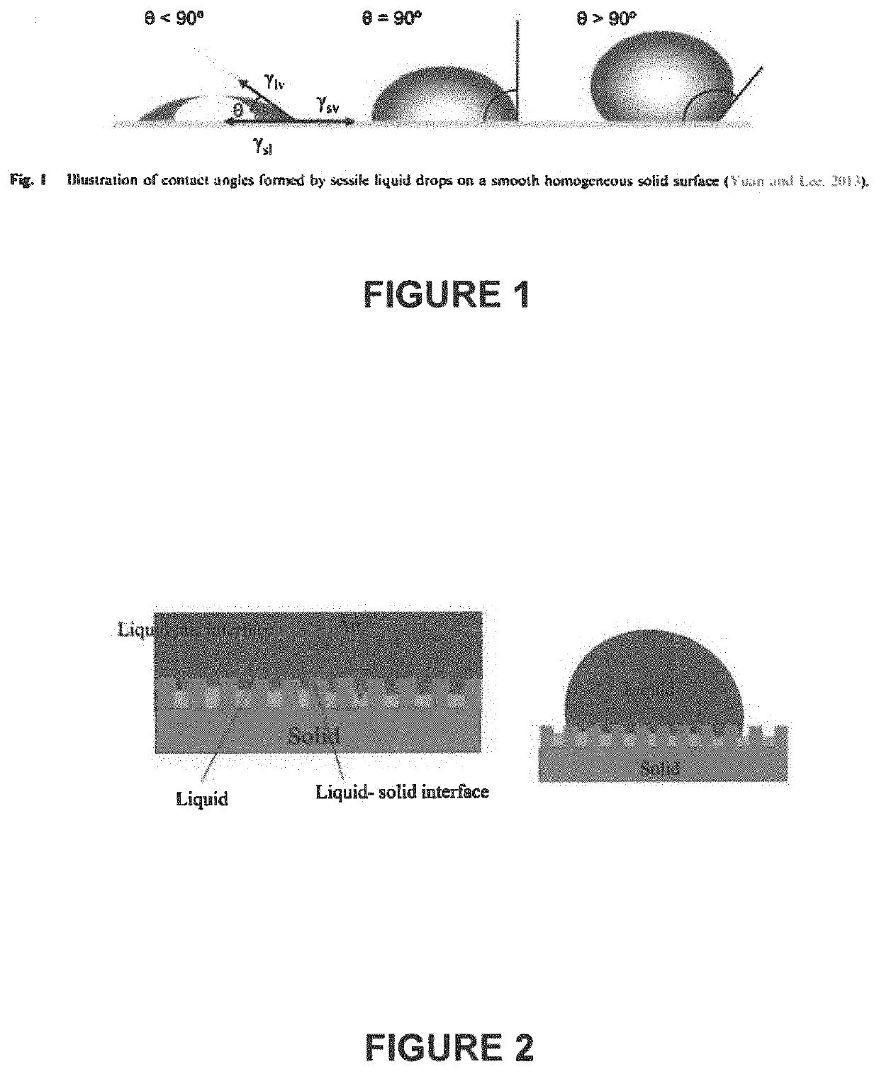
[0035]The present invention contemplates a method of enhancing heat exchanger thermal performance by providing heat exchanger tubing with a textured, hydrophobic exterior surface. In distinction from previous techniques, including non-durable coatings, and relatively expensive metal deposition and the like, the present invention contemplates an economical method for formation of the desired hydrophobic surface, which will exhibit the necessary durability, while facilitating formation in a cost-effective manner. Notably, features of the present invention promote preservation of the textured, hydrophobic surface attenda...


PUM

PropertyMeasurementUnit
contact angleaaaaaaaaaa
distanceaaaaaaaaaa

Abstract

A method of forming a heat exchanger tube, particularly suited for condensing applications, contemplates cold-rolling a metallic strip to emboss a hydrophobic surface texture, to thereby form an embossed surface on the metallic strip. The method includes roll forming the metallic strip to a tubular shape, with the embossed surface on the exterior of the tubular shape, and welding the edges of the roll-formed strip to form a heat exchanger tube. Cold-rolling to emboss a hydrophobic surface texture exhibiting a contact angle of at least about 75° is contemplated, with processing including heat-treatment to minimize degradation of the hydrophobic surface texture, and roll-forming to avoid deformation of the hydrophobic surface texture,

Description

CROSS-REFERENCE TO RELATED APPLICATIONS[0001]This application claims the benefit of the filing date of U.S. Provisional Ser. No. 62 / 872,833, filed Jul. 11, 2019, and U.S. Provisional Ser. No. 62 / 767,108, filed Nov. 14, 2018, which are hereby incorporated by reference in their entirety.FEDERALLY SPONSORED RESEARCH OR DEVELOPMENT[0002]Not Applicable.MICROFICHE / COPYRIGHT REFERENCE[0003]Not Applicable.FIELD OF THE INVENTION[0004]The present invention relates generally to steel tubing used in heat-exchanger applications, and more particularly to a method of forming steel tubing having an embossed, hydrophobic outer surface to provide enhanced heat exchanger performance.BACKGROUND OF THE INVENTION[0005]In a typical heat-exchanger arrangement, such as used in a steam condenser in a power plant, or similar application, condensation of processed steam is typically effected by directing the steam through banks of steel tubing, through which a cooling medium is directed. The condensate is coll...

Claims


Application Information

Patent Timeline
Patent Type & Authority Patents(United States)
IPC IPC(8): B21D53/06F28F1/00
CPCB21D53/06F28F1/00B21D53/02B21C37/0818B21H8/005F28F13/185F28F21/083F28F21/086F28F2245/04
Inventor JANIKOWSKI, DANIEL S.MURPHY, CHARLESLANGE, CHRISTIAN
Owner PLYMOUTH TUBE
Learn More