
Large-angle optical raster scanning system for deep tissue imaging

a scanning system and optical raster technology, applied in the direction of fluorescence/phosphorescence, analysis by material excitation, instruments, etc., can solve the problems of insufficient to meet the nyquist criterion of large fov with micro-optical resolution, and the number of pixel numbers is low, so as to reduce signal strength and the effect of pixel number

Active Publication Date: 2022-05-17
NAT TAIWAN UNIV
View PDF2 Cites 0 Cited by
  • Summary
  • Abstract
  • Description
  • Claims
  • Application Information

AI Technical Summary

Benefits of technology

The invention is related to a system for improving the performance of a resonant scanning mirror used in a microscope or other optical instruments. The system uses a dedicated tube lens with a large field of view and a high-NA objective lens for raster scanning a tissue sample and collecting the resulting fluorescence signal. A pulsed laser source is used to excite the sample, and a graphics processing unit-accelerated interpolation algorithm is used to overcome the distortion caused by the nonlinear speed of the resonant scanning mirror. The system also compensates for reduced signal strength near the edges of the FOV by using a larger number of data points near the edges compared to the center of the FOV. This ensures that the system can meet the requirements of large FOV with micro-optical resolution. The technical effects of this system include improved image quality, reduced distortion, and improved performance of microsopes and other optical instruments.

Problems solved by technology

While extending the scanning angle (and thereby the FOV), the nonlinear speed of a resonant scanning mirror leads to image distortion along the fast X-axis, enforcing one to sample at non-equidistant time points maintaining uniform pixel rate and thereby resulting in lower pixel number, insufficient to fulfil Nyquist Criterion for large FOV with micro-optical resolution.

Method used


Image

  • Large-angle optical raster scanning system for deep tissue imaging
  • Large-angle optical raster scanning system for deep tissue imaging
  • Large-angle optical raster scanning system for deep tissue imaging

Examples


Embodiment Construction

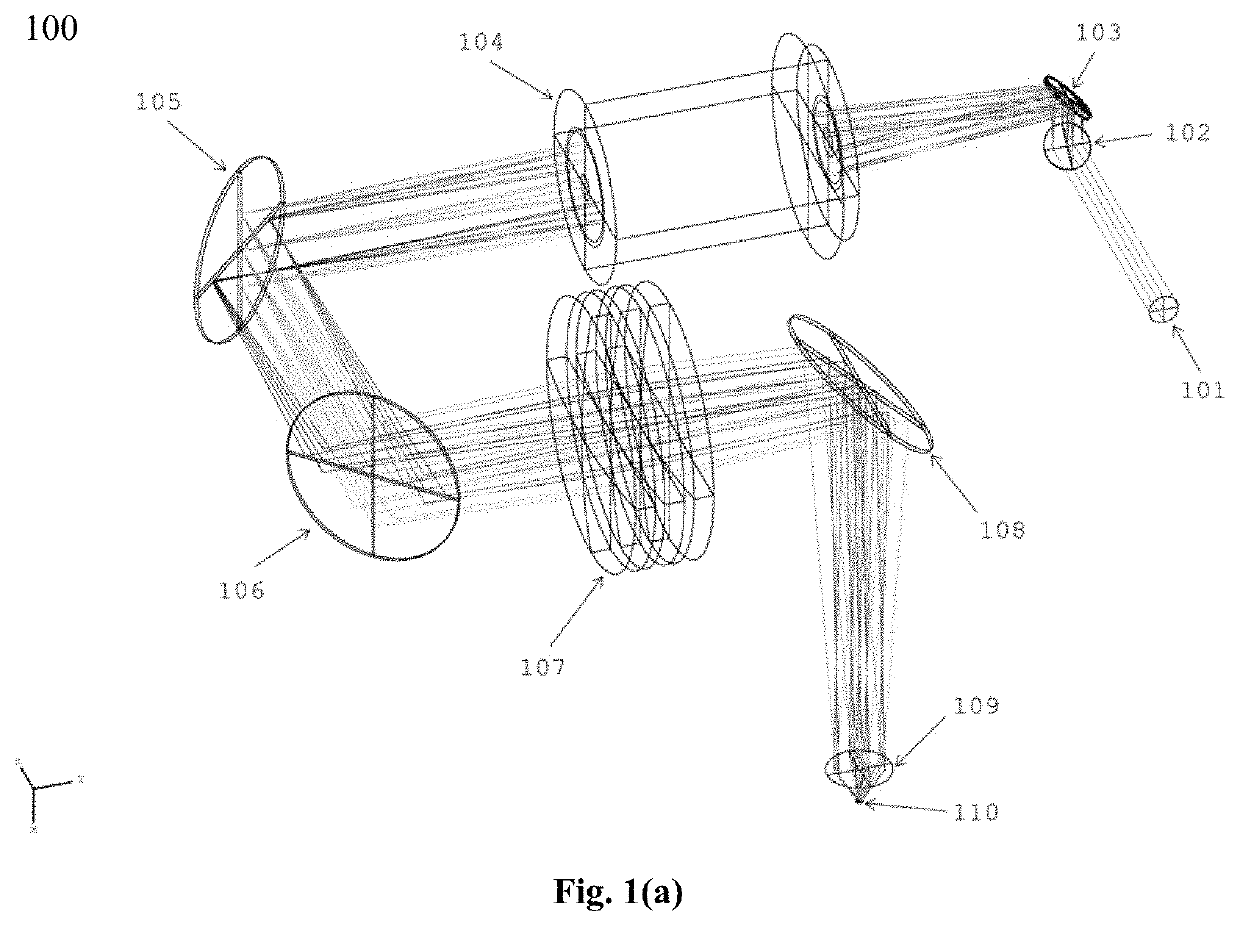
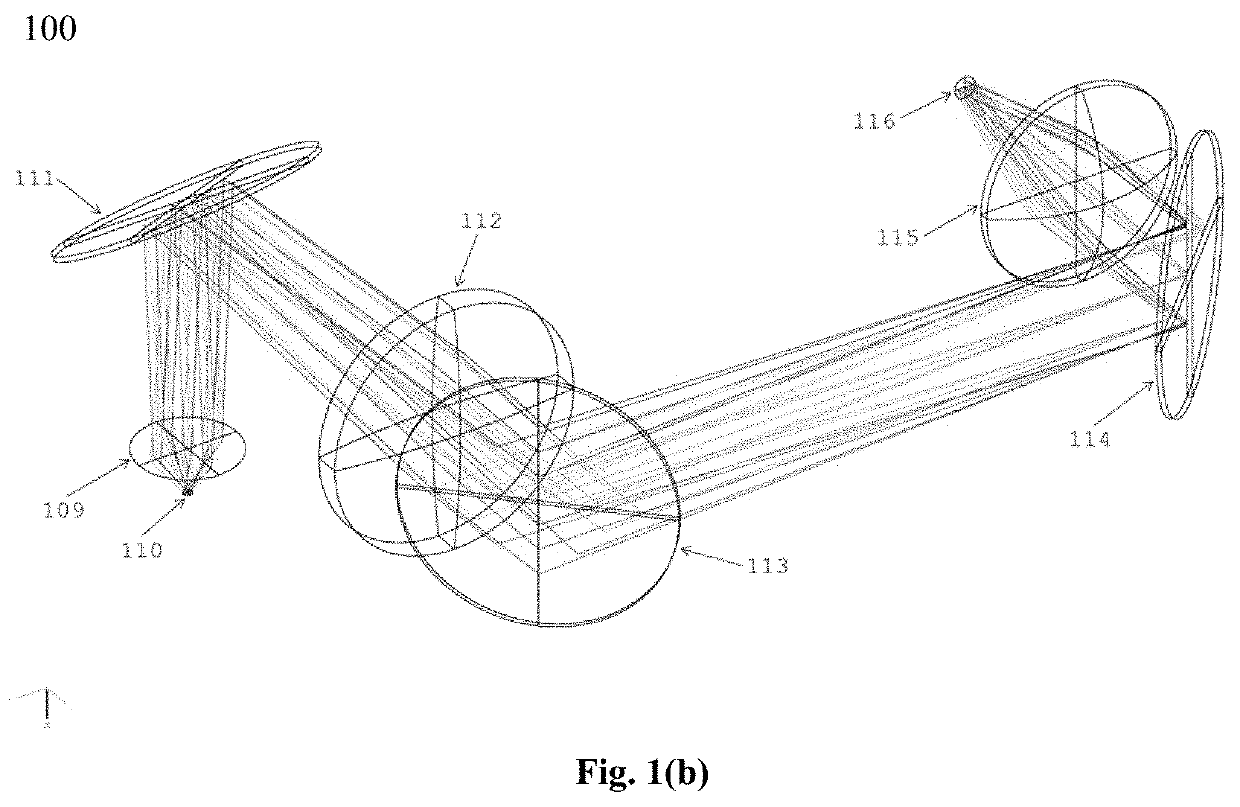
[0019]According to the invention, a large-angle optical raster scanning-system (as shown in FIGS. 1(a), 1(b)) is optimized using ZEMAX, with large scanning angle of up to ˜±7.16° on the back aperture of the high-NA and low magnification objective lens (Olympus-XLUMPlanF1, 20×, 0.95 W, effective focal length (EFL)=9 mm), producing square-FOV of up to 1.6×1.6 mm2. To implement large scanning angle, the invention provides and optimizes a dedicated tube lens combining three plano-convex lenses (Admund Optics: 86-925), each with clear aperture and EFL of 73.5 mm and 500 mm, respectively, resulting in combined EFL of 166.7 mm, and producing beam magnification of 1.515 times with combination of a general scan lens (Thorlabs-LSM05-BB, EFL=110 mm); hence, requiring scanning angle of up to ˜±10.8° over the scan lens to achieve a square-FOV of 1.6×1.6 mm2.

[0020]Using an input beam at λ=1070 nm with a diameter of 9.25 mm and considering the high-NA and low magnification objective lens as a para...


PUM


Abstract

The field of view (FOV) of a nonlinear optical microscope (NLOM) is expected to be large enough for employing high-speed raster scanning on a mesoscale volumetric biological sample. Concurrently, three-dimensional (3D) visualization of fine sub-micron biological structures requires high enough lateral and axial resolutions, enforcing a high numerical aperture (NA) objective lens to be employed, thereby limiting the FOV of an NLOM. The invention is directed to a laser scanning NLOM, or to a large-angle optical raster scanning system, for deep biological tissue imaging with a large FOV of more than one square millimeter, up to 1.6×1.6 mm2, while simultaneously maintaining a sub-femtoliter effective 3D resolution by means of a high-NA and low magnification objective lens and further maintaining a high acquisition speed with synchronized sampling, limited by the repetition rate of a high repetition rate pulsed laser source, thereby exceeding Nyquist Criterion for resolving micro-optical resolution throughout a horizontal FOV of more than one millimeter.

Description

BACKGROUND OF THE INVENTION[0001]Deep-penetration capability of a Nonlinear Optical Microscope (NLOM) makes it suitable for three-dimensional (3D) imaging compared to CCD-based and single-photon imaging systems. To employ high-speed raster scanning on a mesoscale volumetric biological sample, the field of view (FOV) of an NLOM is expected to be large enough. However, to extend the FOV of an NLOM, either an increased scanning angle or usage of low magnification and low numerical aperture (NA) objective, both degrade image quality in terms of optical resolution. On the contrary, 3D visualization of fine sub-micron biological structures requires high enough lateral and axial resolutions, enforcing a high-NA objective to be employed, and furthermore, the extended FOV must be resolved by high-speed sampling fulfilling Nyquist-Criterion, thereby making FOV-extension beyond one square millimeter with sub-femtoliter effective 3D resolution, while not compromising with the acquisition speed,...

Claims


Application Information

Patent Timeline
IPC IPC(8): G02B21/00G01N21/64G02B21/02
CPCG02B21/0048G01N21/64G02B21/0032G02B21/0072G02B21/0076G02B21/02G01N2201/068G01N2201/06113
Inventor SUN, CHI-KUANGBORAH, BHASKAR JYOTI
Owner NAT TAIWAN UNIV
Learn More