Low-sidelobe plate array antenna

a low-sidelobe plate, array antenna technology, applied in the structure of radiating elements, individual energised antenna arrays, particular array feeding systems, etc., can solve the problems of increasing insertion loss, micro-strip array antennas can fulfill a wide band, and cannot fulfill high frequency, high efficiency or high gain

Active Publication Date: 2022-07-05
NINGBO UNIV
View PDF4 Cites 2 Cited by
  • Summary
  • Abstract
  • Description
  • Claims
  • Application Information

AI Technical Summary

Benefits of technology

[0008]The technical issue to be settled by the invention is to provide a low-sidelobe plate array antenna, which has a low sidelobe, is simple in structure, low in cost and suitable for mass production, and has a wide frequency bandwidth and high efficiency.
[0051]the sixth conversion block is symmetrical with the fourth conversion block in the front-back direction, a front end surface of the sixth conversion block is connected to and entirely overlaps with the rear end surface of the second metal block, the front end surface of the third conversion block, the front end surface of the fourth conversion block, a rear end surface of the fifth conversion block and a rear end surface of the sixth conversion block are used as the fourth output terminals of the first-level H-type E-plane waveguide power divider respectively, the front end surface of the first rectangular block is connected and attached to the rear end surface of the third metal block, a length of the first rectangular block in the left-right direction is 0.6λ, a distance from a left end of the front end surface of the first rectangular block to a left end of the rear end surface of the third metal block is equal to a distance from a right end of the front end surface of the first rectangular block to a right end of the rear end surface of the third metal block, and the rear end surface of the first rectangular block is used as the input terminal of the first-level H-type E-plane waveguide power divider. In this structure, the first-level H-type power dividers in the feed layer perform input and output in the same direction, so that the structure is compact, ultra-wideband and high-efficiency feeding of the plate antenna is realized, and miniaturization is facilitated.
[0056]In this structure, the single ridge step, the H-plane step and the E-plane step are arranged in the E-plane rectangular waveguide-single ridge waveguide transducer to realize impedance matching and to reduce the return loss caused by structural discontinuities, so that the plate array antenna has a good wideband transmission property, uniform feeding to the radiation units in the radiation layer is fulfilled, the dominant-mode bandwidth can be expanded, and ultra-wideband and high-efficiency feeding of the array antenna is realized.
[0057]Compared with the prior art, the invention has the following advantages: each radiation unit in the radiation layer is constituted by two first radiation assemblies and two second radiation assemblies, wherein the two first radiation assemblies are parallelly arranged left and right and are spaced apart from each other, the first radiation assembly on the left will overlap with the first radiation assembly on the right after being moved rightwards by 0.9λ, the two second radiation assemblies are also arranged left and right and are spaced apart from each other, the second radiation assembly on the left will overlap with the second radiation assembly on the right after being moved rightwards by 0.9λ, the two second radiation assemblies are located behind the two first radiation assemblies, a center distance between the second radiation assembly on the left and the first radiation assembly on the left is 0.9λ, and a center distance between the second radiation assembly on the right and the first radiation assembly on the right is 0.9λ; each first radiation assembly comprises a first rectangular bar, a first rectangular cavity, a second rectangular cavity and a third rectangular cavity, wherein the first rectangular cavity, the second rectangular cavity and the third rectangular cavity are sequentially arranged from top to bottom, there exists an azimuth deviation between the three rectangular cavities, a center of the first rectangular bar, a center of the first rectangular cavity, a center of the second rectangular cavity and a center of the third rectangular cavity are located on the same center line, the first radiation assembly on the left will overlap with the second radiation assembly on the left after being moved downwards by 0.9λ and then being rotated clockwise by 180° around the center line, and the first radiation assembly on the right will overlap with the second radiation assembly on the right after being moved downwards by 0.9λ and then being rotated clockwise by 180° around the center line.
[0058]The first rectangular cavity, the second rectangular cavity and the third rectangular cavity in the first radiation assembly are stacked in presence of an azimuth deviation to form a three-layer coupled structure so as to optimize a multi-level radiation structure of traditional plate antennas into a one-level radiation structure, so that the profile height of the plate antennas is greatly decreased, and higher assembly precision can be realized easily.
[0059]The low-profile and miniaturized design restrains the property of cross polarization of the traditional plate antennas, obviously improves the gain and aperture efficiency of the plate antennas; in addition, the first rectangular bar located in the first rectangular cavity can better restrain cross polarization and reduce the sidelobe; therefore, the low-sidelobe plate array antenna of the invention has a low sidelobe, is simple in structure, low in cost and suitable for mass production, and has a wide frequency bandwidth and high efficiency.

Problems solved by technology

However, when the frequency or antenna array size increases, the insertion loss will be increased due to conductor losses and dielectric losses of the micro-strip array antennas.
Thus, the micro-strip array antennas can fulfill a wide band, but cannot fulfill high frequency, high efficiency or high gain.
However, the beam direction of the waveguide slot traveling wave array antennas varies with the frequency, which results in inconsistent directions of antenna beams within a wideband range, and the waveguide slot traveling wave array antennas can only be used within an extremely narrow bandwidth, and the frequency band cannot be expanded.
According to the first solution, the power distribution proportion of the feed layer is controlled to adjust the energy distribution of the radiation layer to reduce the sidelobe; however, when this solution is used to reduce the sidelobe, the main lobe will become wider, the gain will be decreased, and it is impossible to gain an extremely low sidelobe under the condition where a narrow main lobe is guaranteed and the gain is not sacrificed.
However, due to the addition of the polarization layer, the cost of the antennas may be increased by 20% during mass production.
This waveguide slot array antenna has a wide band, a high gain and a low sidelobe, but has the following problems: 1, the radiation layer has too many structure layers which cannot be processed one by one, the assembly structure is complicated, so that mass production is unavailable; 2, the radiation layer adopts a coupling cavity divided into four parts, so that the relative bandwidth is narrow, and a wider frequency bandwidth cannot be obtained; 3, the low-sidelobe property is realized by means of repeated rotation of the several radiation units in the radiation layer, so that the efficiency of the antennas is reduced.

Method used


Image

  • Low-sidelobe plate array antenna
  • Low-sidelobe plate array antenna
  • Low-sidelobe plate array antenna

Examples


Embodiment Construction

[0072]The invention will be further expounded below in conjunction with the accompanying drawings and embodiments.

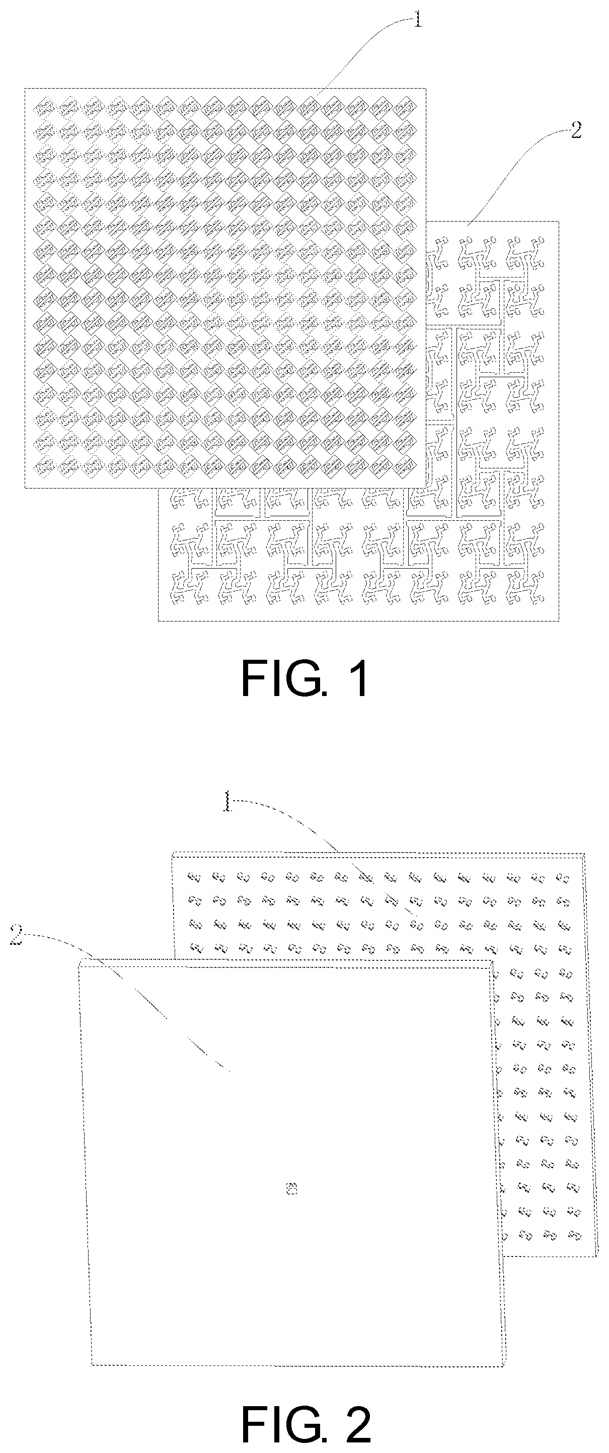
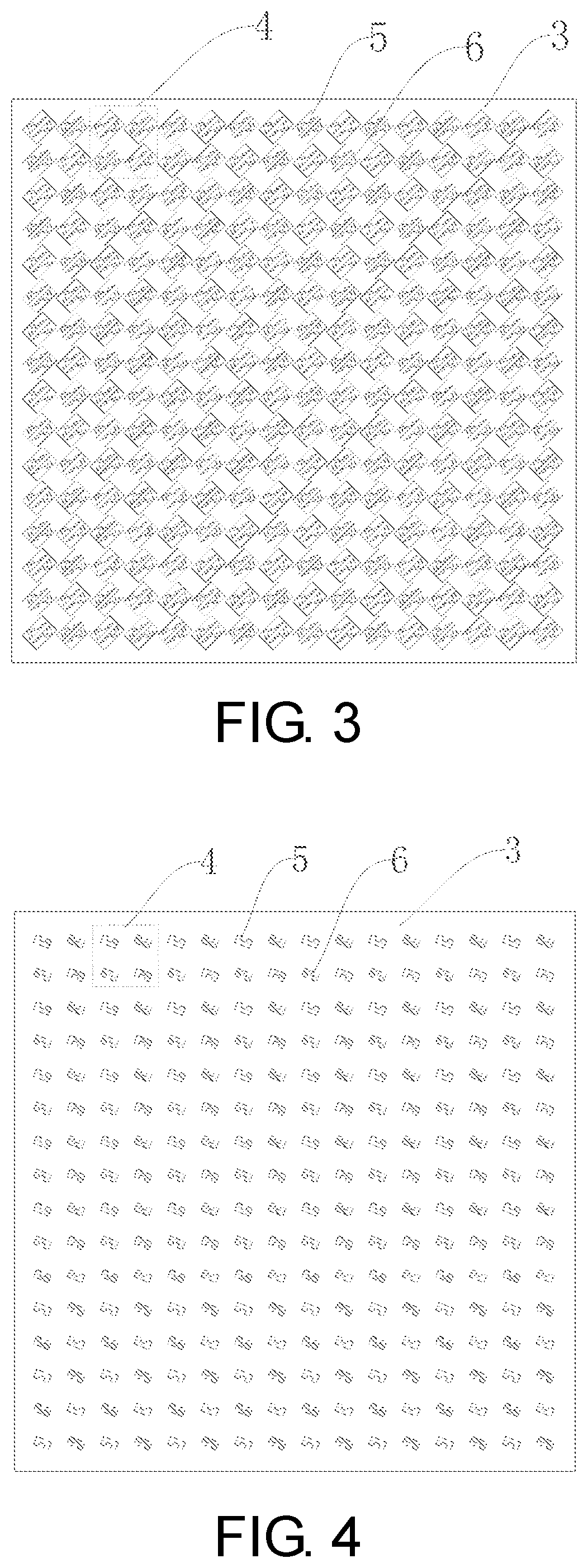
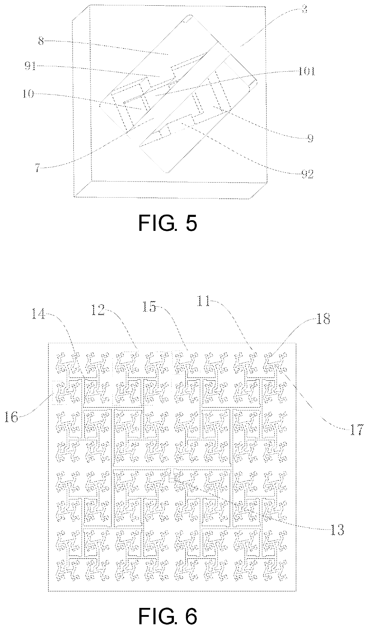
[0073]Embodiment: as shown in FIG. 1 and FIG. 2, a low-sidelobe plate array antenna comprises a radiation layer 1 and a feed layer 2, wherein the radiation layer 1 is superimposed on the feed layer 2, the feed layer 2 is used to output 4*n2 TE10 mode signals, the radiation layer 1 has 4*n2 input terminals and 4*n2 output terminals, the 4*n2 TE10 mode signals output by the feed layer 2 are accessed to the 4*n2 input terminals of the radiation layer 1 in a one-to-one correspondence, the 4*n2 output terminals of the radiation layer 1 are used to radiate the 4*n2 TE10 mode signals output by the feed layer 2 to a free space in a one-to-one correspondence, n=2(k-1), and k is an integer greater than or equal to 3; as shown in FIG. 3-FIG. 5, the radiation layer 1 comprises a first plate 3 and a radiation array disposed on the first plate 3, wherein the first plate 3 is a rectang...


PUM


Abstract

A low-sidelobe plate array antenna includes a radiation layer and a feed layer. The radiation layer is superimposed on the feed layer and includes a first plate and a radiation array disposed on the first plate. The radiation array is formed by n2 radiation units which are distributed in 2(k-1) rows and 2(k-1) columns. Each radiation unit in the radiation layer is constituted by two first radiation assemblies and two second radiation assemblies. Each first radiation assembly comprises a first rectangular bar, a first rectangular cavity, a second rectangular cavity and a third rectangular cavity. The first rectangular cavity, the second rectangular cavity and the third rectangular cavity in the first radiation assembly are stacked in presence of an azimuth deviation to form a three-layer coupled structure, and the first rectangular bar located in the first rectangular cavity can better restrain cross polarization and reduce the sidelobe.

Description

CROSS-REFERENCE TO RELATED APPLICATION[0001]This application claims the priority benefit of China application serial no. 202010417832.9, filed on May 18, 2020. The entirety of the above-mentioned patent application is hereby incorporated by reference herein and made a part of this specification.TECHNICAL FIELD[0002]The invention relates to a plate array antenna, in particular to a low-sidelobe plate array antenna.DESCRIPTION OF RELATED ART[0003]In recent years, high-performance array antennas which have a high sensitivity, a wide band, a low profile and a low sidelobe and characterized by multiple frequency bands and low costs have been widely used in the fields of radar, communication, remote sensing and metering, and spatial technology. Existing common array antennas mainly include micro-strip array antennas and plate array antennas.[0004]The micro-strip array antennas are featured by low profile, low cost and low weight and are easy to machine. However, when the frequency or ante...

Claims


Application Information

Patent Timeline
Patent Type & Authority Patents(United States)
IPC IPC(8): H01Q15/00H01Q1/38H01Q21/00H01Q21/06H01Q25/02
CPCH01Q15/0053H01Q1/38H01Q21/0031H01Q21/061H01Q25/02H01Q21/064H01Q13/10H01Q1/36H01Q1/50H01Q13/18
Inventor YOU, YANGHUANG, JIFUZHANG, LINGYOU, QINGCHUNLU, YUNLONG
Owner NINGBO UNIV
Why Eureka
Try Eureka