
Electrode plate for lead-acid battery and manufacturing method thereof

a technology of electrode plates and lead-acid batteries, which is applied in the direction of current conducting connections, cell components, cell component details, etc., can solve the problems of poor discharge performance, difficult handling at the assembling time, and a large voltage drop in the expansion portion, so as to reduce the risk of thinning the lug part by grinding it, reduce the risk of thinning the lug part, and remove the effect of easy and complete removal

Inactive Publication Date: 2001-11-22
GS YUASA CORP
View PDF0 Cites 23 Cited by
  • Summary
  • Abstract
  • Description
  • Claims
  • Application Information

AI Technical Summary

Benefits of technology

[0018] According to the invention, the electrode plate using the expanded grid body excellent in discharge performance and productivity can be provided particularly as a large-sized lead-acid battery electrode plate.
[0067] 2) After passing through flash drying furnace: The active material became hard as compared with that just after pasting, and can be easily removed without being caught in the rotating brush of the grinding machine.

Problems solved by technology

handling at the assembling time becomes difficult to perform (warpage, deformation of electrode plate because of insufficient strength); and
voltage drop in the expansion portion becomes remarkably large and poor discharge performance results.
However, improvement in the discharge performance is insufficient for a large-sized electrode plate of which is large in the height direction as compared with the width direction.
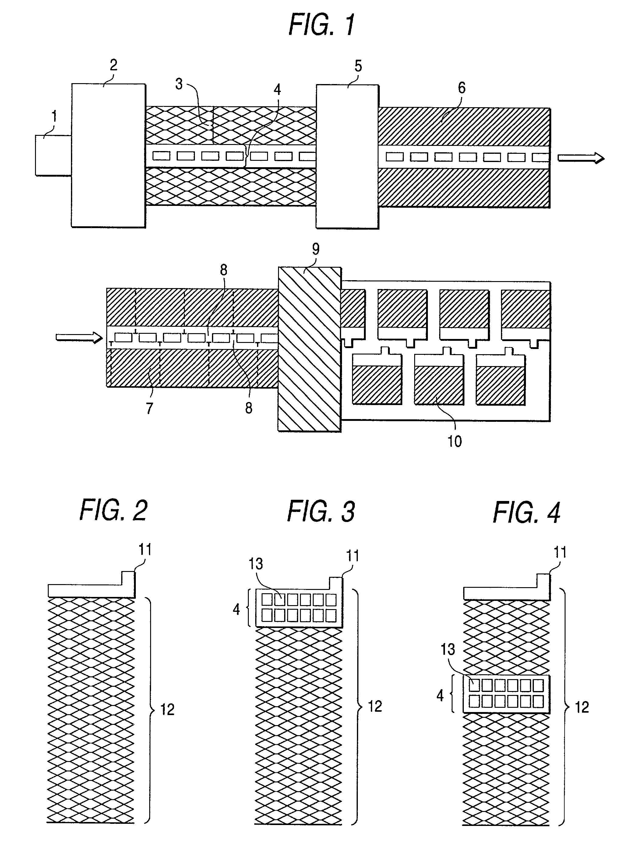
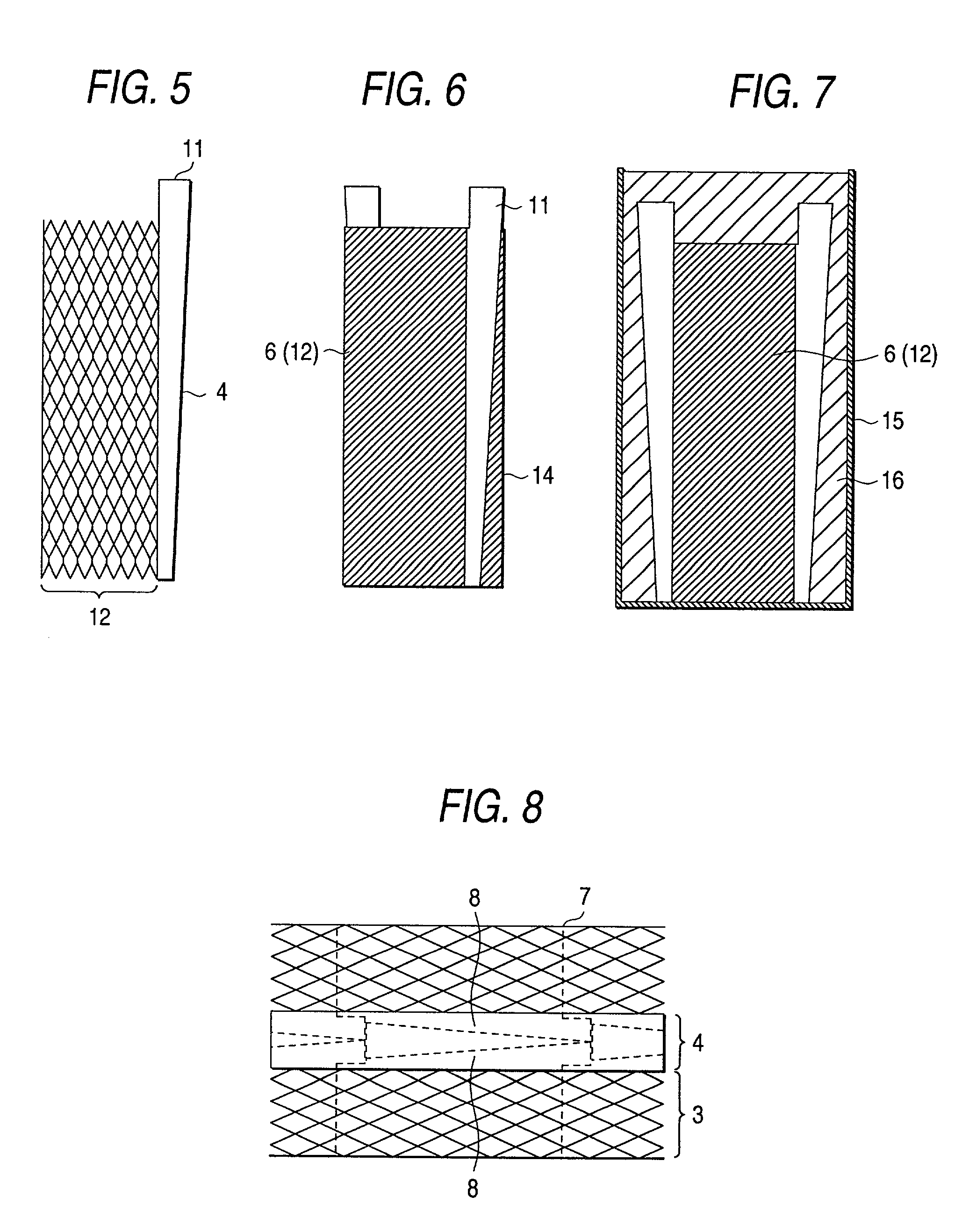
Thus, as shown in FIG. 6, if an electrode plate using the grid body of this shape is superposed on an electrode plate different in polarity to manufacture a battery, a portion 14 not overlapping the adjacent electrode plate occurs and the efficiency of active material availability decreases, leading to capacity shortage of the battery.
Particularly, in a valve regulated sealed lead-acid battery using a fine glass fiber separator, it is known that a battery with a compression degree of the electrode plate and the separator is inferior in life performance, and there is a possibility that capacity lowering at an early stage will occur because of shortage of the pressure degree in the portion not overlapping the adjacent electrode plate.
Further, a grid body extends in a gap 16 between the electrode plate and the battery container 15, whereby adhesion properties of grid members with active material worsen, leading to lowering of the battery capacity.
However, if a decrease in the scrap loss is given a high priority, an increase in the grid body mass and battery capacity shortage caused by decrease of the active material filling amount introduce a problem.
As shown in FIG. 1, to fill an active material into the expanded grid body of the conventional shape, the active material is prevented from being deposited on current collection lug parts 8, because welding becomes extremely difficult to perform if an active material is deposited on electrode plate lug parts when the electrode plate of the same polarity lug parts are welded at the battery assembling process.
In fact, the expanded grid bodies expanded in the width direction are scarcely used because of the problems.

Method used


Image

  • Electrode plate for lead-acid battery and manufacturing method thereof
  • Electrode plate for lead-acid battery and manufacturing method thereof
  • Electrode plate for lead-acid battery and manufacturing method thereof

Examples


first embodiment

[0041]

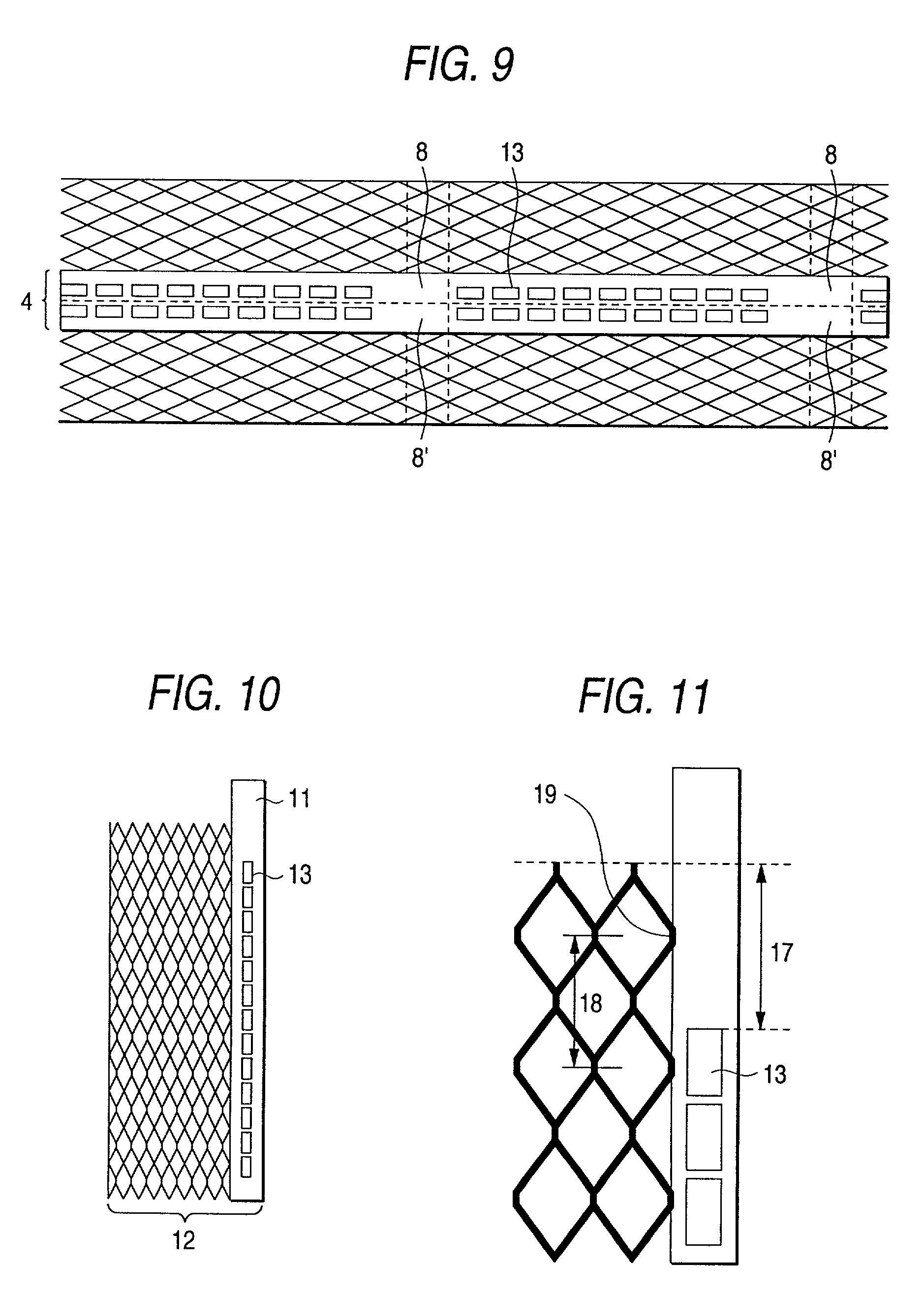
[0042] A sheet 2.0 mm thick manufactured by rolling a lead-calcium-tin alloy was consecutively expanded with a non-expansion port 4 left in the center as shown in FIG. 9. Subsequently, the non-expansion portion 4 of the expanded sheet was formed with openings 13 intermittently and a part of the expansion portion was cut at a position indicated by a dotted line 7, whereby a current collector lug part 8 was formed and an expanded grid body of the present invention (grid height H except lug part=400 mm, grid width W=140 mm) as shown in FIG. 10 was manufactured. The openings were made by stamping about 45% of the non-expansion portion when electrode plates were separated. Considering the electrical conductivity, the strength, the active material mass, and the mass of each electrode plate, a proper percentage of the openings is 30% to 70% to the non-expansion portion per electrode plate. This time, each opening was made rectangular, but the shape may be changed as desired depending...

second embodiment

[0057]

[0058] In the first embodiment, it was found that the grid body of the invention has excellent discharge performance and life performance. An example of a method of actually manufacturing electrode plates consecutively will be discussed. FIG. 24 shows a sequence of steps.

[0059] To manufacture the expanded electrode plate shown in FIG. 10, a lead-calcium-tin alloy rolled sheet 2 mm thick and 130 mm wide was expanded to both sides with a non-expansion portion left in the center by a reciprocation-type expanding machine. Next, openings were stamped to provide the shape shown in FIG. 9. If the expanded sheet is cut in the length direction, electrode plates can be taken out two at a time; paraffin as a parting agent of an active material was applied only to a part 8' corresponding to electrode plate lug part of one series of electrode plates. The sheet was passed through a pasting machine 5 for filling active material paste 6 into the full face of the sheet. At the pasting process,...

third embodiment

[0062]

[0063] In the sequence of the electrode plate manufacturing steps described in the second embodiment, the timing of removing the active material on the electrode plate lug part using the grid body of the invention was studied. The active material removal timings listed below are possible and thus an experiment was conducted at the timings. Before an active material was pasted into an expansion sheet, paraffin was applied to the part which becomes a lug part as a parting agent.

[0064] 1) Just after filling, 2) after passing through flash drying furnace, 3) after completion of curing, and 4) just before assembling.

[0065] The Results Are as Follows:

[0066] 1) Just after pasting: The active material was soft, a rotating brush of a grinding machine was clogged with the active material, and it became hard to remove the active material with time.

[0067] 2) After passing through flash drying furnace: The active material became hard as compared with that just after pasting, and can be eas...


PUM

PropertyMeasurementUnit
heightaaaaaaaaaa
widthaaaaaaaaaa
thicknessaaaaaaaaaa

Abstract

A lead-acid battery electrode plate is manufactured by consecutively supplying a lead or lead alloy sheet; leaving a part in the vicinity of the center of the sheet as a non-expansion portion and expanding both sides like mesh to form a grid body; filling active material paste into the grid body; and cutting the grid body to predetermined dimensions. In the lead-acid battery electrode plate, the non-expansion portion forms a current collector part of the electrode plate along an expansion portion in an up and down direction of the electrode plate. One or more openings are made in a part of the non-expansion portion. A part of the non-expansion portion is projected above the position of an upper margin of the cut expansion portion as a current collector lug part. When the current collector lug part is placed upside, the expansion direction is the width direction of the electrode plate.

Description

BACKGROUND OF THE TNVENTION[0001] 1. Field of the Invention[0002] This invention relates to an expanded grid body mainly used with a large-sized lead-acid battery and a manufacturing method of an electrode plate using the expanded grid body.[0003] 2. Description of the Related Art[0004] As a manufacturing method of pasted-type lead-acid battery electrode plate, for example, there is the following manner as shown in FIG. 1. That is, a lead or lead alloy sheet 1 is expanded like mesh by an expanding machine 2. A current collector lug part (simply referred lug part) is formed in a non-expansion portion 4. A grid body which is an expansion portion 3 is filled with an active material paste. Thereafter, the grid body is cut by a cutter 9 to separate electrode plates of a predetermined size. This method is high in productivity and so-called expanded electrode plates manufactured by the method are uniform and the mass of the grid body relative to the active material can be decreased, so tha...

Claims


Application Information

Patent Timeline
Patent Type & Authority Applications(United States)
IPC IPC(8): H01M4/20H01M4/74H01M4/82H01M50/50
CPCH01M2/20H01M4/20Y10T29/10H01M4/82Y02E60/126H01M4/745Y02E60/10H01M50/50
Inventor OMAE, TAKAOKAMADA, AKIRAWATANABE, MASASHI
Owner GS YUASA CORP
Learn More