

Battery and process for preparing the same
- Summary
- Abstract
- Description
- Claims
- Application Information
AI Technical Summary
Benefits of technology
Problems solved by technology
Method used
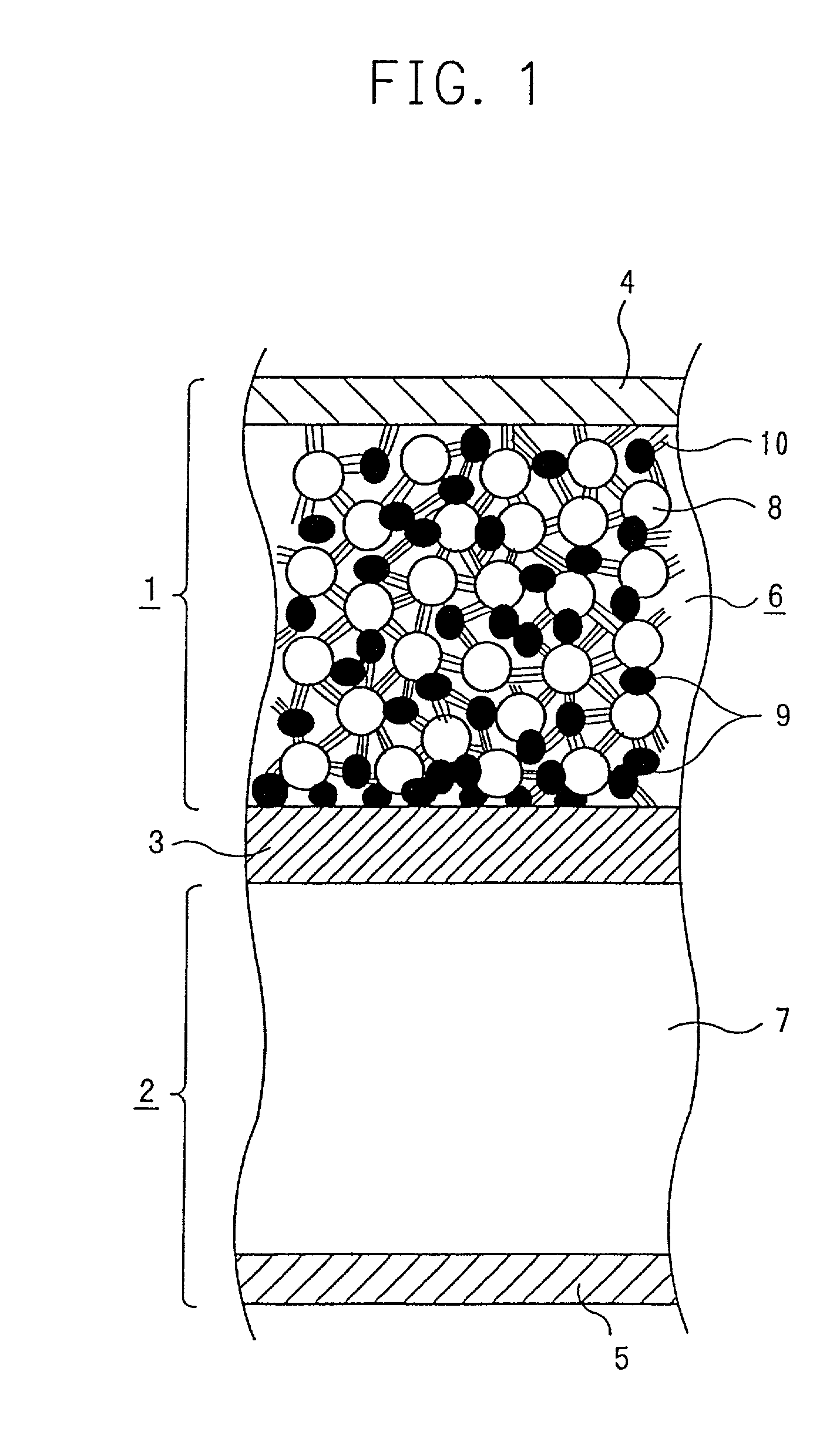
Image

Examples
example 2
[0119] The ratio of the electronically conductive material in preparation of the positive electrode in Example 1 was varied. FIG. 4 illustrates the relationship between a ratio of the electronically conductive material and volume specific resistance of each electrode and the relationship between a ratio of the electronically conductive material and discharging capacitance. Specifically, FIG. 4 illustrates the relationship between a ratio of the electronically conductive material to 100 parts by weight of the total solid content of the electrode (herein the positive electrode) of the battery and volume specific resistance ((a) in the figure) of each electrode, and the relationship between the ratio of the electronically conductive material to 100 parts by weight of the total solid content of the electrode (herein the positive electrode) of the battery and discharging capacitance ((b) in the figure).
[0120] As shown in FIG. 4, when at most 0.5 part by weight of the electronically condu...
example 3
[0122] Particle size of the electronically conductive material in preparation of the positive electrode in Example 1 was varied. FIG. 5 illustrates the relationship between the particle size of the electronically conductive material and resistance of each electrode ((a) in FIG. 5) and the relationship between the particle size of the electronically conductive material and discharging capacitance ((b) in FIG. 5).
[0123] When the particle size of the electronically conductive material is at most 0.05 .mu.m, filling ratio of the electronically conductive material is decreased, which means that volume of the electronically conductive material per a unit volume of the positive electrode active material layer is increased, namely that an amount of the positive electrode active material is decreased. Therefore, when the particle size of the electronically conductive material is at most 0.05 .mu.m, discharging capacitance is decreased. On the other hand, when the particle size of the electro...
example 4
[0125] Pellets of an electronically conductive material (prepared by mixing 60 parts by weight of carbon black in the form of fine particles and 40 parts by weight of polyethylene) having a volume specific resistance of 0.2 .OMEGA..multidot.cm at a room temperature and a volume specific resistance of 20 .OMEGA..multidot.cm at 135.degree. C. were finely pulverized by using Ball Mill to obtain fine particles of the electronically conductive material.
[0126] By using the fine particles of the electronically conductive material, an electrode (herein a positive electrode) was prepared in the same manner as in Example 1, and furthermore, a battery was prepared in the same manner of preparing the negative electrode and the battery as in Example 1.
[0127] Table 3 shows the average particle size of the electronically conductive material, resistance of each electrode, and discharging capacitance.
[0128] In this example, since the electronically conductive material was pulverized according to Bal...
PUM
 Abstract
Description
Claims
Application Information