A novel lithium ion flow battery

a lithium ion flow and lithium ion technology, applied in the direction of indirect fuel cells, cell components, cell component details, etc., can solve the problems of increasing the internal resistance of the battery, and affecting the flow of the electrode suspension solution, so as to reduce the requirement for electronic conductivity, improve the effect of current collection and electrical conduction, and reduce the amount of conductive additives

Active Publication Date: 2016-11-10
BEIJING HAWAGA POWER STORAGE TECH
View PDF2 Cites 6 Cited by
  • Summary
  • Abstract
  • Description
  • Claims
  • Application Information

AI Technical Summary

Benefits of technology

[0029]1) the design of the sandwich composite structure layers composed of a cathode current collector, a separator and an anode current collector allows the dimension of the battery reaction chamber to be flexibly designed according to the viscosity of the electrode suspension solution without increasing the polarization resistance of the battery, thereby solving the current conflict restriction existing between the dimension of the reaction chamber and the polarization resistance of the lithium ion flow battery;
[0030]2) the design of the sandwich composite structure layers allows the electrode suspension solution to achieve excellent effects of current collection and electrical conduction in the presence of less conductive additive. Thus, compared with existing lithium ion flow battery, the novel lithium ion flow battery lowers requirement on the electronic conductivity of the electrode suspension solutions, i.e. the contents of the conductive additives in the electrode suspensions solution can be lowered, and augments the energy density and fluidity of the electrode suspension solutions;
[0031]3) the dimension of the battery reaction chamber can be enlarged randomly, even when the electrode suspension solution has a high viscosity, to decrease flow resistance of the viscous electrode suspension solutions in the battery reaction chambers, thereby decreasing drive loss of electrode suspension solutions and improving energy efficiency of battery.

Problems solved by technology

Compared with the electrolyte of an all-vanadium redox flow battery, the electrode suspension solution of the lithium ion flow battery is more viscous and relatively more difficult to flow, thus there is a high requirement on design for the reaction chamber of the battery reactor, in which case an excessively narrow reaction chamber could be detrimental to the flow of the electrode suspension solution.
The problem existing in the above design is that, taking into account the fluidity of electrode suspension solution, the larger the gap distance between the current collector and the separator is (i.e., the larger the space of the reaction chamber is), the more easily the viscous electrode suspension solution flows, otherwise too small gap distance will make the electrode suspension solution flow difficulty; while taking into account the polarization resistance, the smaller the gap distance between the current collector and the separator is (i.e., the smaller the space of the reaction chamber is), the smaller the current collecting internal resistance is, otherwise too large gap distance will increase the conductive distance of electrons and ions in the electrode suspension solution, thereby increasing the internal resistance of the battery and lowering the charge-discharge conversion efficiency.
Therefore, the above interacting factors restrict the design flexibility for dimension of the reaction chamber, and affect the performance of the lithium ion flow battery.

Method used


Image

  • A novel lithium ion flow battery
  • A novel lithium ion flow battery
  • A novel lithium ion flow battery

Examples


example 1

[0041]This example provides sandwich composite structure layers of the lithium ion flow battery.

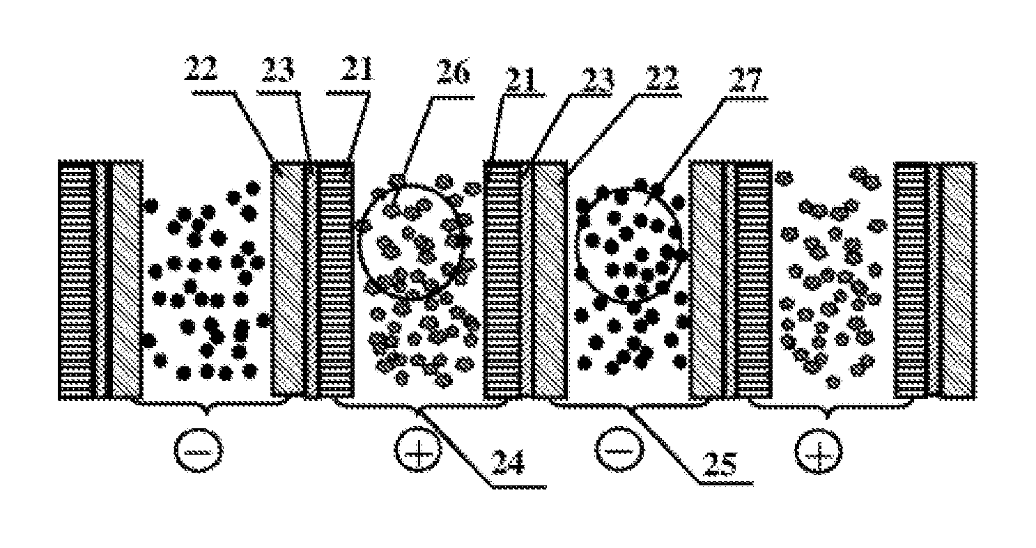
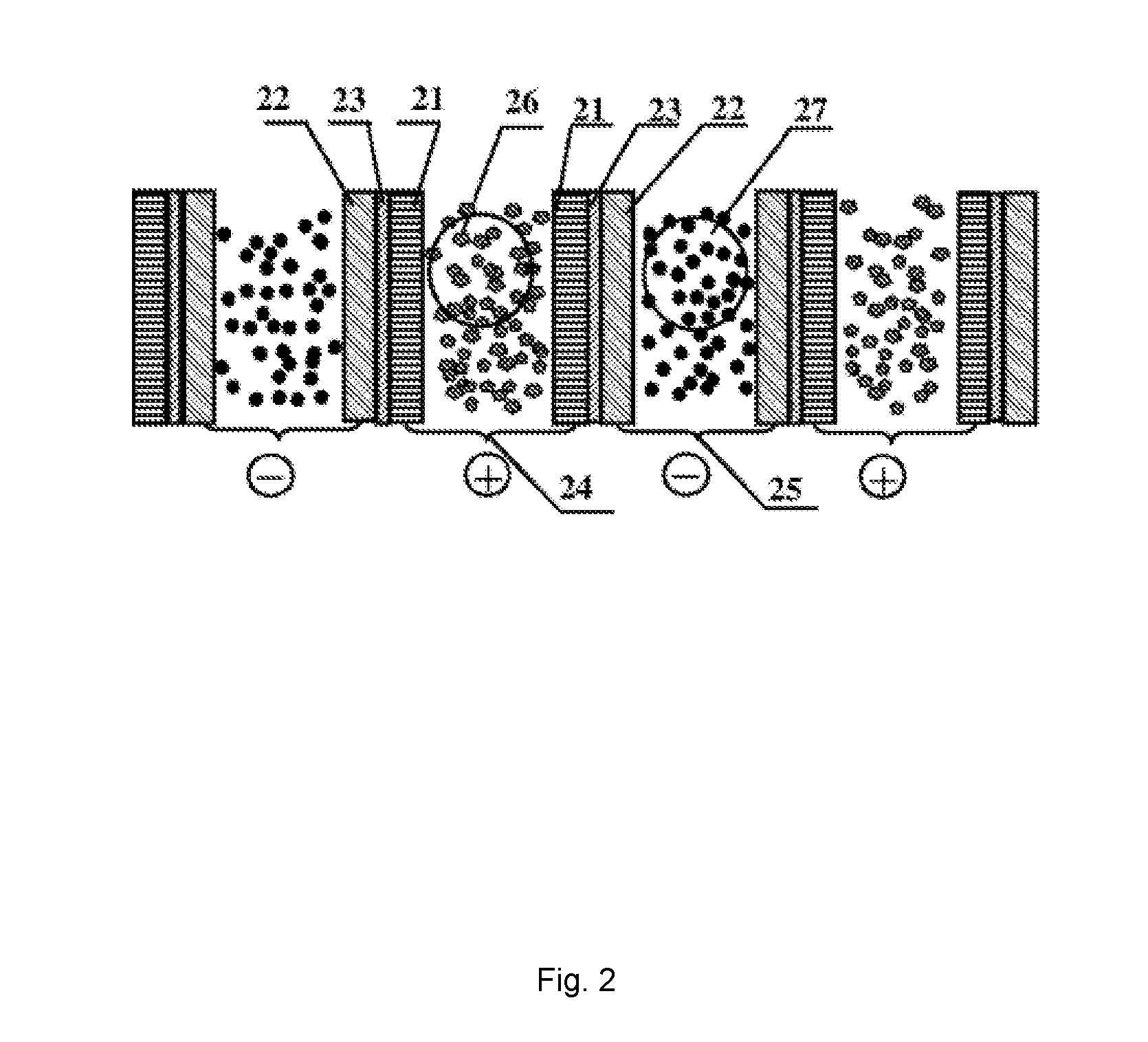
[0042]The structure of reaction chamber of the lithium ion flow battery is shown in FIG. 2. In the example, a PP / PE / PP porous composite film is used as an separator 23. The separator 23 is spray-coated at both surface thereof with a cathode current collector 21 and an anode current collector 22, respectively. The cathode current collector 21 is a conductive coating formed of a mixture of carbon nanotube with a mass percent of 90% and polyvinylidene fluoride, and has a thickness of 20 μm. The anode current collector 22 is a conductive coating formed of a mixture of carbon fiber with content of 90% and polyvinylidene fluoride, and has a thickness of 20 μm.

[0043]Further, two adjacent cathode current collectors 21 in which contained a cathode suspension solution 26 form a cathode reaction chamber 24. In the example, the distance between the two adjacent cathode current collectors 21 forming t...

example 2

[0045]This example provides another sandwich composite structure layers of the lithium ion flow battery, in which the lithium ion flow battery has a structure similar to that in example 1, by reference to the schematic structural view of FIG. 2.

[0046]In the example, a conductive polymer electrolyte film, which is a composite gel polymer electrolytes compounded by three parts of polymer matrix, liquid organic plasticizer and lithium salt, is selected as a separator. Porous carbon fiber conductive cloth is selected as both the cathode current collector having a thickness of 900 μm and the anode current collector having the same thickness of 900 μm. Sandwich composite structure layers are constituted by bonding the cathode current collector, the separator and the anode current collector.

[0047]In the example, the width of the cathode reaction chamber 24 is 5 mm and the width of the anode reaction chamber 25 is 5 mm.

example 3

[0048]This example provides another sandwich composite structure layers of lithium ion flow battery which has a structure similar to examples 1 and 2, by reference to the schematic structural view of FIG. 2.

[0049]In the example, a bilayer-structured PE porous film is selected as a separator.

[0050]The cathode current collector is a composite structure of porous aluminum foil and porous conductive coatings, and has a thickness of 0.08 mm, wherein the aluminum foil has a thickness of 0.05 mm and the meshes of the aluminum foil are in quadrate shape with a pore diameter of 0.5 mm and through-hole porosity of 60%. The anode current collector is a composite structure of porous copper foil and porous conductive coatings, and has a thickness of 0.08 mm, wherein the copper foil has a thickness of 0.05 mm and the meshes of the copper foil are in circular shape with a pore diameter of 0.5 mm and through-hole porosity of 60%.

[0051]Further, the porous conductive coating is a mixture of carbon po...


PUM

PropertyMeasurementUnit
distanceaaaaaaaaaa
distanceaaaaaaaaaa
pore diameteraaaaaaaaaa

Abstract

A lithium ion flow battery comprising cathode current collectors (21), an anode current collector (22), a cathode reaction chamber (24), an anode reaction chamber (25), a separator (23), a cathode suspension solution (26) and an anode suspension solution (27), wherein the cathode and anode current collectors are located at both sides of the separator respectively and are in close contact with the separator to form sandwich composite structure layers of the cathode current collector, the separator and the anode current collector; and in that several sandwich composite structure layers are arranged in sequence in an order that current collectors with the same polarity are oppositely arranged, and the electrode suspension solution continuously or intermittently flows in a battery reaction chamber between adjacent sandwich composite structure layers. Thus, the size of the battery reaction chamber can be flexibly designed according to the viscosity of the electrode suspension solution without increasing the polarization internal resistance of the battery, thereby solving the restriction conflict existing in the existing lithium ion flow battery between the size of the battery reaction chamber and the polarization internal resistance of the battery.

Description

FIELD OF THE INVENTION[0001]The present invention pertains to a technical field of chemical energy storage battery, and particularly relates to lithium ion flow battery.BACKGROUND OF THE INVENTION[0002]Lithium ion flow battery is a newly developed chemical battery technology, which integrates the advantages of lithium ion battery and flow battery, and thus becomes a novel rechargeable battery with independent power output and energy storage capacity, high energy density and low cost. Lithium ion flow battery has tremendously wide market prospects in wind power generation, photovoltaic power generation, power grid peak load regulation, power station distribution, municipal transportation and the like.[0003]Lithium ion flow battery is composed of a cathode suspension solution tank, an anode suspension solution tank, a battery reactor, a liquid pump or pneumatic control system, and sealed conduits, wherein the cathode suspension solution tank contains a mixture of cathode materials par...

Claims


Application Information

Patent Timeline
Patent Type & Authority Applications(United States)
IPC IPC(8): H01M4/86H01M8/20H01M2/16H01M8/18H01M8/0202
CPCH01M4/8626H01M2/1673H01M8/20H01M8/188H01M8/0202H01M8/0289H01M8/0297H01M8/0232H01M8/0234H01M8/0239H01M8/0243H01M8/0293Y02E60/10Y02E60/50H01M50/46
Inventor CHEN, YONGCHONGFENG, CAIMEIZHANG, YANPINGZHANG, PINGWANG, QIUPING
Owner BEIJING HAWAGA POWER STORAGE TECH
Why Eureka
Try Eureka