
Flameless combustor process heater

Inactive Publication Date: 2002-02-07
SHELL OIL CO
View PDF18 Cites 99 Cited by
  • Summary
  • Abstract
  • Description
  • Claims
  • Application Information

AI Technical Summary

Benefits of technology

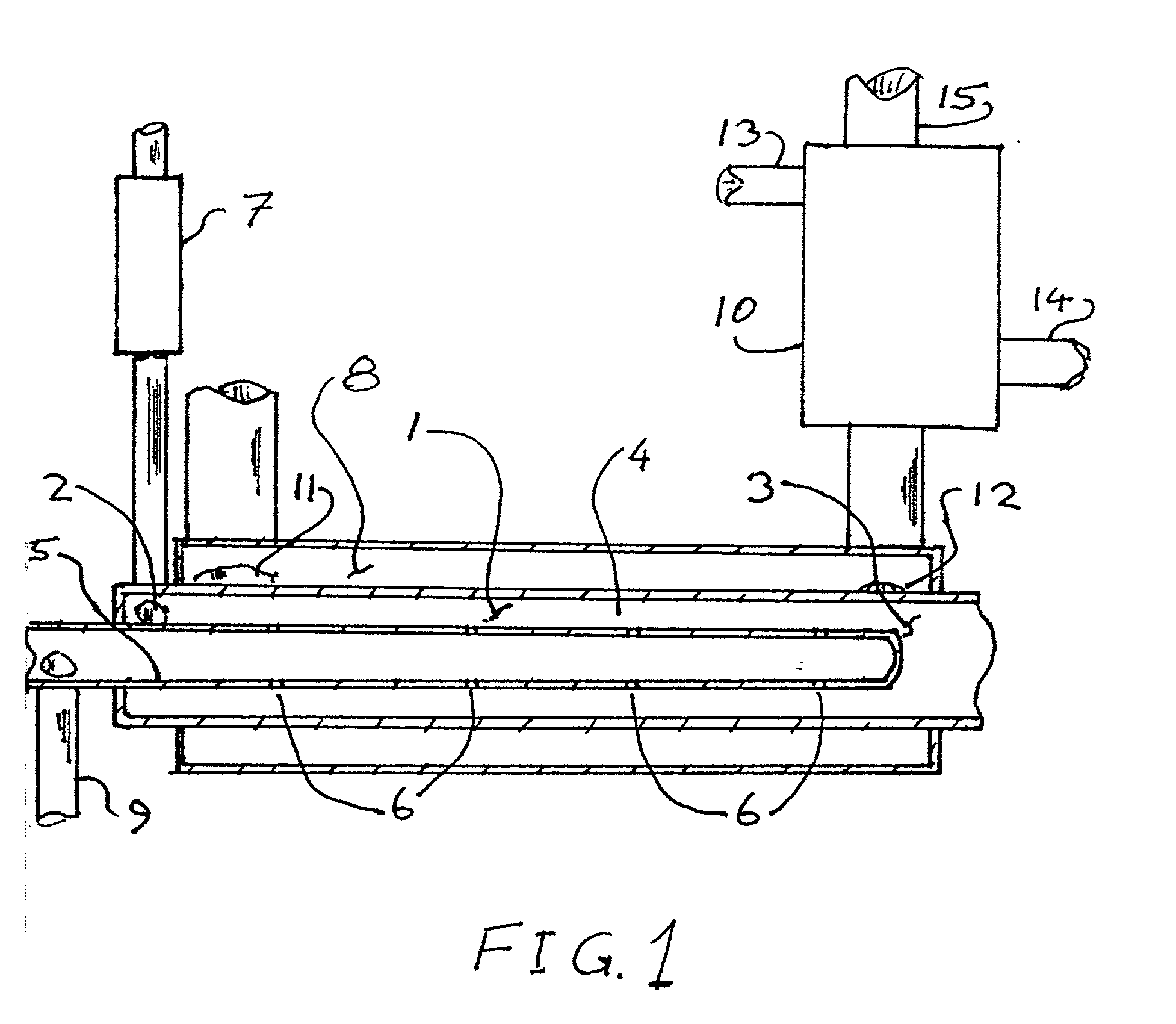
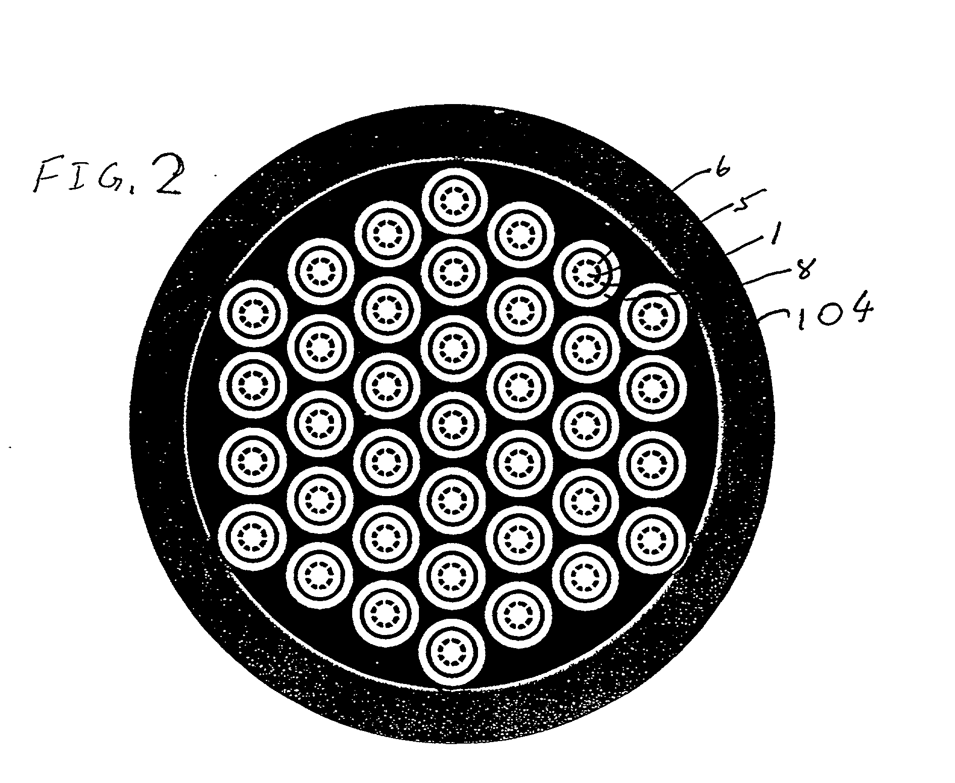
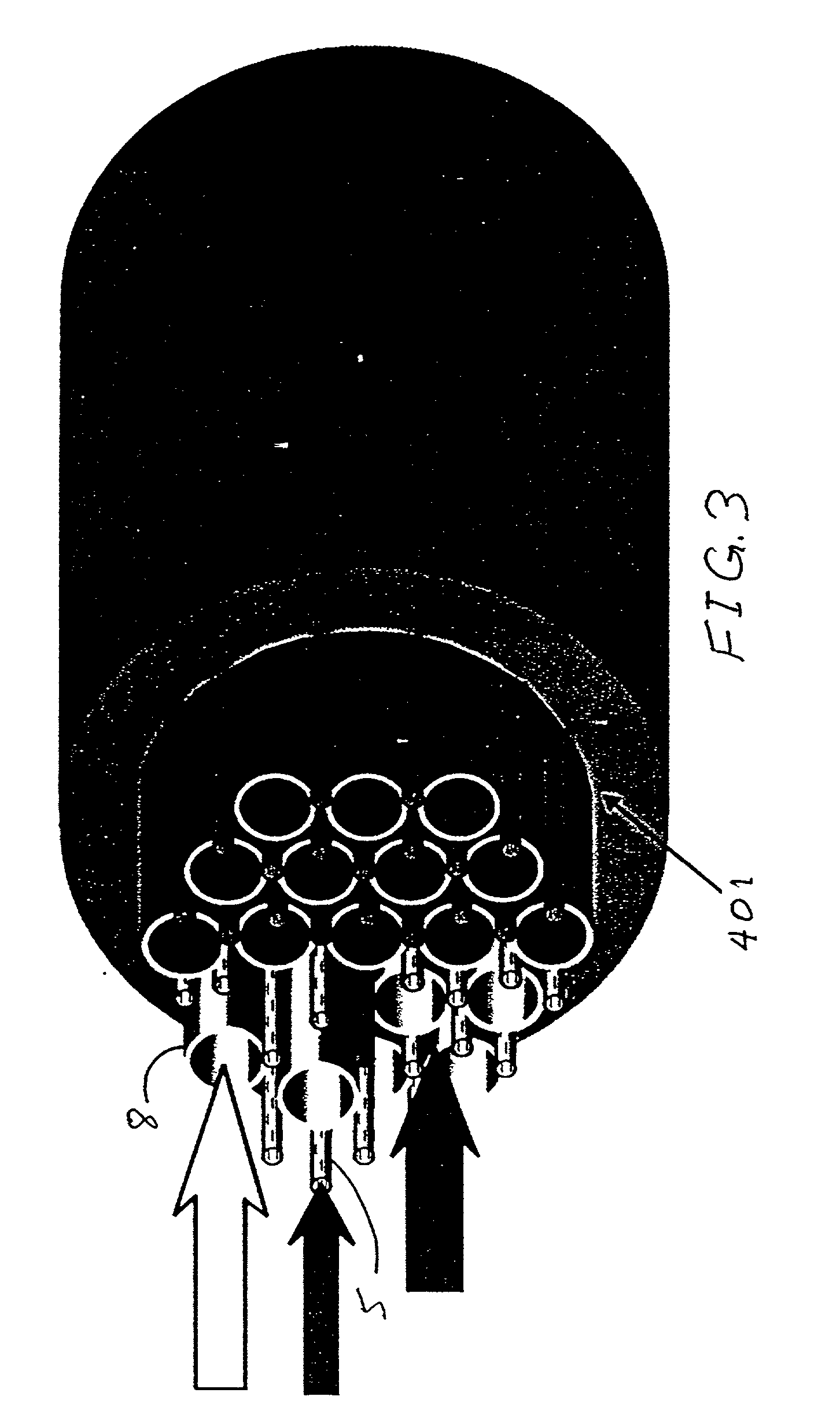
[0013] These and other objects are achieved by a process heater comprising: an oxidation reaction chamber, the oxidation reaction chamber having an inlet for oxidant, an outlet for combustion products, and a flow path between the inlet and the outlet; a fuel conduit capable of transporting a fuel mixture to a plurality of fuel nozzles within the oxidation reaction chamber, with each nozzle along the flowpath between the inlet and the outlet, each nozzle providing communication from within the fuel conduit to the oxidation chamber; a preheater in communication with the oxidation chamber inlet, the preheater capable of increasing the temperature of the oxidant to a temperature resulting in the combined oxidant and fuel from the fuel nozzle closest to the oxidation chamber inlet being greater than the autoignition temperature of the combined oxidant and fuel from the fuel nozzle closest to the oxidation chamber inlet; and a process chamber in a heat exchange relationship to the oxidation reaction chamber wherein the heat transferred from the oxidation section does not causes the temperature of the mixture within the oxidation reaction chamber in the vicinity of each fuel nozzle to decrease below the auto ignition temperature of the combined mixture in the oxidation chamber in the vicinity of that fuel nozzle.
[0014] The distributed combustion process heater of the present invention can be utilized to provide a controllable heat flux into a process chamber, from a heat source which has a uniform temperature, and very low creation of NO.sub.x. The uniform temperatures can be utilized to increase average temperatures without exceeding maximum temperatures, or to reduce the cost of materials.

Problems solved by technology

But it is difficult to maintain uniform heat transfer in a fired furnace.
This variation is compounded by difficulty in measuring these temperatures.
This effect snow-balls, and can result in failure of the tube if not detected and corrective action taken.
Decreasing firing then lowers heat transfer around the hot spot, and generally is detrimental to performance of the heater.
Lengths of tubes in fired furnaces are also generally limited due to physical constraints.
In some steam-methane reforming furnaces multiple levels of burners are provided in order to distribute radiant heat more evenly to the tubes, but even with multiple levels of burners, the vertical distance over which burners can be provided is limited because of the difficulty of providing fuel and air distribution with varying amounts of draft in the furnace.
These elbows are common points of problems due to uneven flow and temperatures, and possible erosion along the inside radius.
In certain areas, emission of NO.sub.x is limited, and expensive measures such as flue gas treatments such as Selective Catalytic Reduction DeNox systems are occasionally required.
Burner systems are available which reduce generation of NO.sub.x by controlling combustion temperatures, but the combustion temperatures are difficult to control, and even under ideal conditions, a significant amount of NO.sub.x is generated.
Another problem with typically fired process heaters is the limited efficiency of the radiant section of the heater.
Even when combustion air preheat is provided, the combustion air preheat typically does not bring the temperature of the combustion air to near flame temperatures.
These component are said to reduce and delay the onset of coke formation, but do not eliminate the formation of coke.
But like treatments to the feedstocks, they are only marginally effective.
These methods avoid the disadvantages of fired furnaces, but incur additional capital and / or operating costs when compared to fired furnace heaters.
These temperatures are generally limited by metallurgical limitations of materials that are economical and consistency of the heat transfer to the tubes.

Method used


Image

  • Flameless combustor process heater
  • Flameless combustor process heater
  • Flameless combustor process heater

Examples


Embodiment Construction

[0017] The process heater of the present invention eliminates the firebox of a conventional process heater and provides uniform heat flux at a controlled temperature level. The fire box is replaced by, for example, concentric tubes that may be in coils, or straight. Fuel and oxidant is mixed in stages and at a temperature that results in oxidation of the fuel without producing a flame, thus eliminating the flame as a radiant source of high level heat, and replaces the flame with a flowing stream of high temperature level gas. In an endothermic process, this can result in higher temperatures within metallurgical constraints, thus resulting in many processes in improved conversions, selectivities and / or yields and reduced byproduct production. Elimination of irregular temperatures also reduces risk of failures of tubulars due to local hot spots. Radiant efficiency of flameless combustion according to the present invention can also be greater, resulting in lower energy consumption.

[001...


PUM


Abstract

A process heater is provided utilizing flameless combustion, the process heater having: an oxidation reaction chamber, the oxidation reaction chamber having an inlet for oxidant, an outlet for combustion products, and a flow path between the inlet and the outlet; a fuel conduit capable of transporting a fuel mixture to a plurality of fuel nozzles within the oxidation reaction chamber, each nozzle providing communication from within the fuel conduit to the oxidation chamber, with each nozzle along the flowpath between the inlet and the outlet; a preheater in communication with the oxidation chamber inlet, the preheater capable of increasing the temperature of the oxidant to a temperature resulting in the combined oxidant and fuel from the fuel nozzle closest to the oxidation chamber inlet being greater than the autoignition temperature of the combined oxidant and fuel from the fuel nozzle closest to the oxidation chamber inlet; and a process chamber in a heat exchange relationship to the oxidation reaction chamber wherein the heat transferred from the oxidation section does not causes the temperature of the mixture within the oxidation reaction chamber in the vicinity of each fuel nozzle to decrease below the auto ignition temperature of the combined mixture in the oxidation chamber in the vicinity of that fuel nozzle.

Description

[0001] This application claims priority to provisional application No. 60 / 062,439 filed Oct. 8, 1997.[0002] The invention relates to a process heater for high temperature reactions with improved control of heat transfer.BACKGROUND TO THE INVENTION[0003] High temperature, typically endothermic, reactions such as steam methane reforming to form hydrogen from steam and hydrocarbons, and pyrolysis of hydrocarbons to produce olefins are typically carried out in furnace tubes with direct fired radiant heat transfer to the outside surface of the tubes, and flowing reactants on the inside of the tubes. Direct fired heat is often beneficial because of the high temperature level of heat required, high heat flux required, and relatively low capital cost of the furnace. But it is difficult to maintain uniform heat transfer in a fired furnace. Therefore, these furnace tube must be operated at an average tube skin temperature that is somewhat below the maximum allowable tube skin temperature beca...

Claims


Application Information

Patent Timeline
IPC IPC(8): B01J19/00C01B3/38C10G9/00F23C99/00F23M20/00F27D99/00
CPCF23C99/00F23C2900/99001F23C2900/99006F23L2900/15042Y02E20/342Y02E20/34F23C13/00
Inventor SHAH, RASHMI K.
Owner SHELL OIL CO
Learn More