
Complex objective lens and method for manufacturing the same and optical pickup device and optical recording/reproducing apparatus

a technology of optical pickup and objective lens, which is applied in the field of optical systems, can solve the problems of difficult production of thick second lens by glass press molding, lens having a small center radius of curvature cannot be very thick, and the object lens comprising two lenses would cost more. to achieve the effect of increasing the tolerance of axis deviation

Inactive Publication Date: 2002-03-07
PIONEER CORP
View PDF8 Cites 16 Cited by
  • Summary
  • Abstract
  • Description
  • Claims
  • Application Information

AI Technical Summary

Benefits of technology

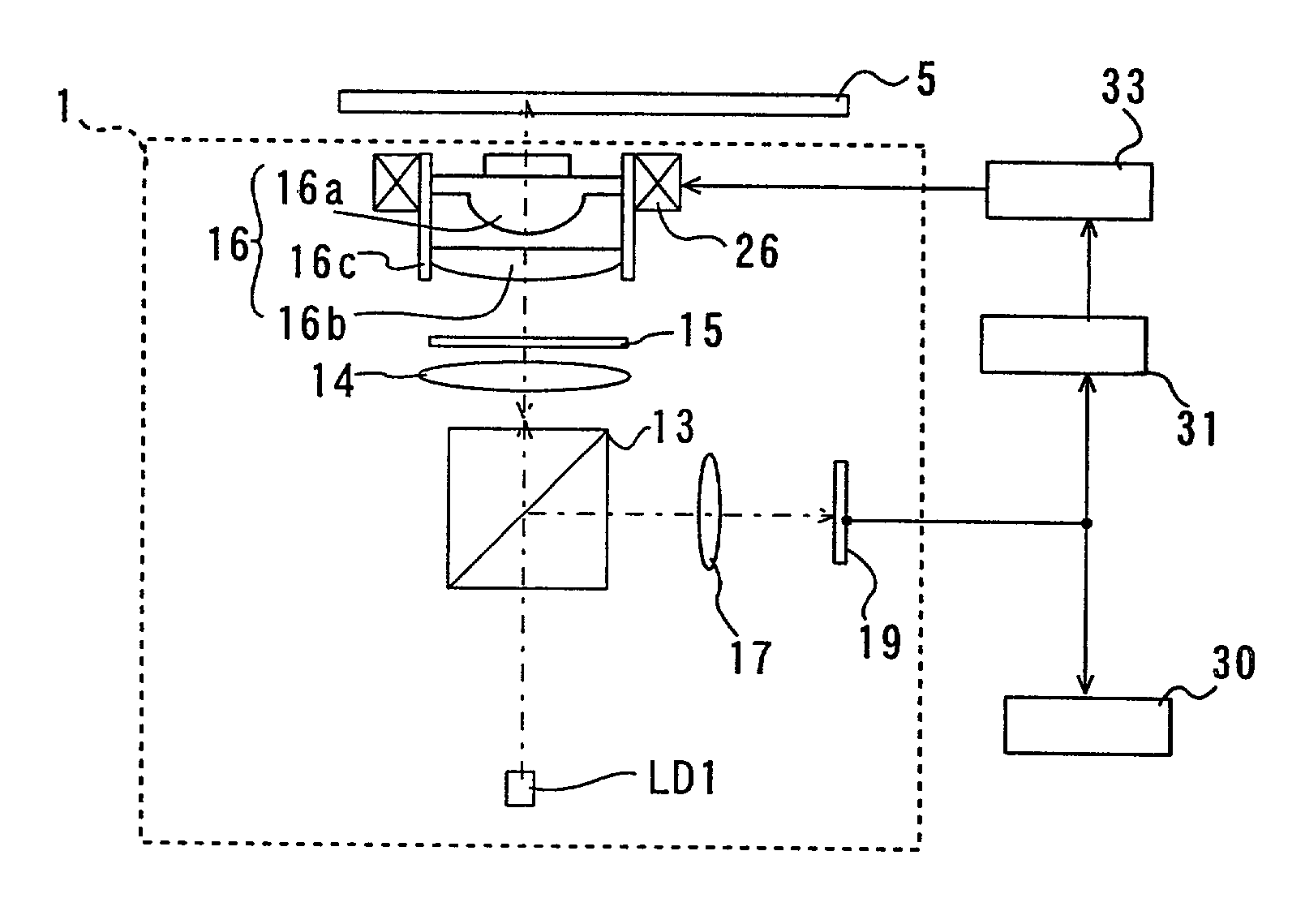
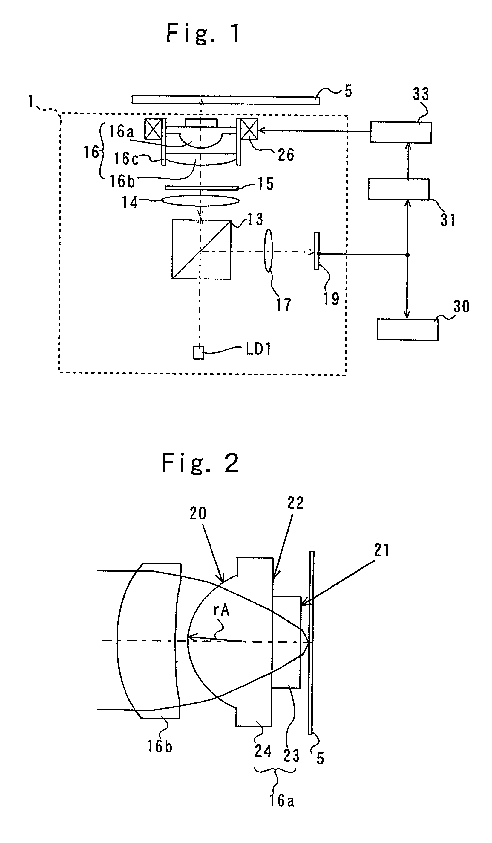
[0052] The optical detector supplies the demodulating circuit 30 and the error detecting circuit 31 with an electric signal in accordance with an optical spot image formed near the center of the light receiving surface 19 thereof. The demodulating circuit 30 generates a recording signal on the basis of the electric signal. The error detecting circuit 31 generates a focusing error signal, a tracking error signal, and other servo signals on the basis of the electric signal to supply each actuator with each driving signal through the driving circuit 33 of the actuator, so that the actuator can servo control and drive the objective lens unit 16 in accordance with each driving signal.
[0059] The left side of formula (1) is determined by the conditions that the preformed glass ball has a radius larger than the radius of a ball having the same volume as the volume of the aspherical surface portion 24. The right side of formula (1) is determined by the volume conditions that, by using a preformed glass ball having a volume smaller than the volume of the convention objective lens consisting of a lens group set including the flat portion, separate two pieces parts can be individually formed so as to make a complex objective lens without adjustment.
[0061] In addition to the features of the first embodiment, the materials of the parallel flat portion 23 or second optical element and an aspherical surface portion 24 or first optical element are selected so that the refractive index of the aspherical surface portion is larger than that of the parallel flat portion, in the second embodiment. Such a material selection enables to increase a tolerance of axis deviation of the first and second optical elements form the center optical axis, since a luminous flux entering through the aspherical surface portion to the parallel flat portion is refracted so as to converge into a point. As a result, the aspherical surface portion does not have to provide a large power of converging light.
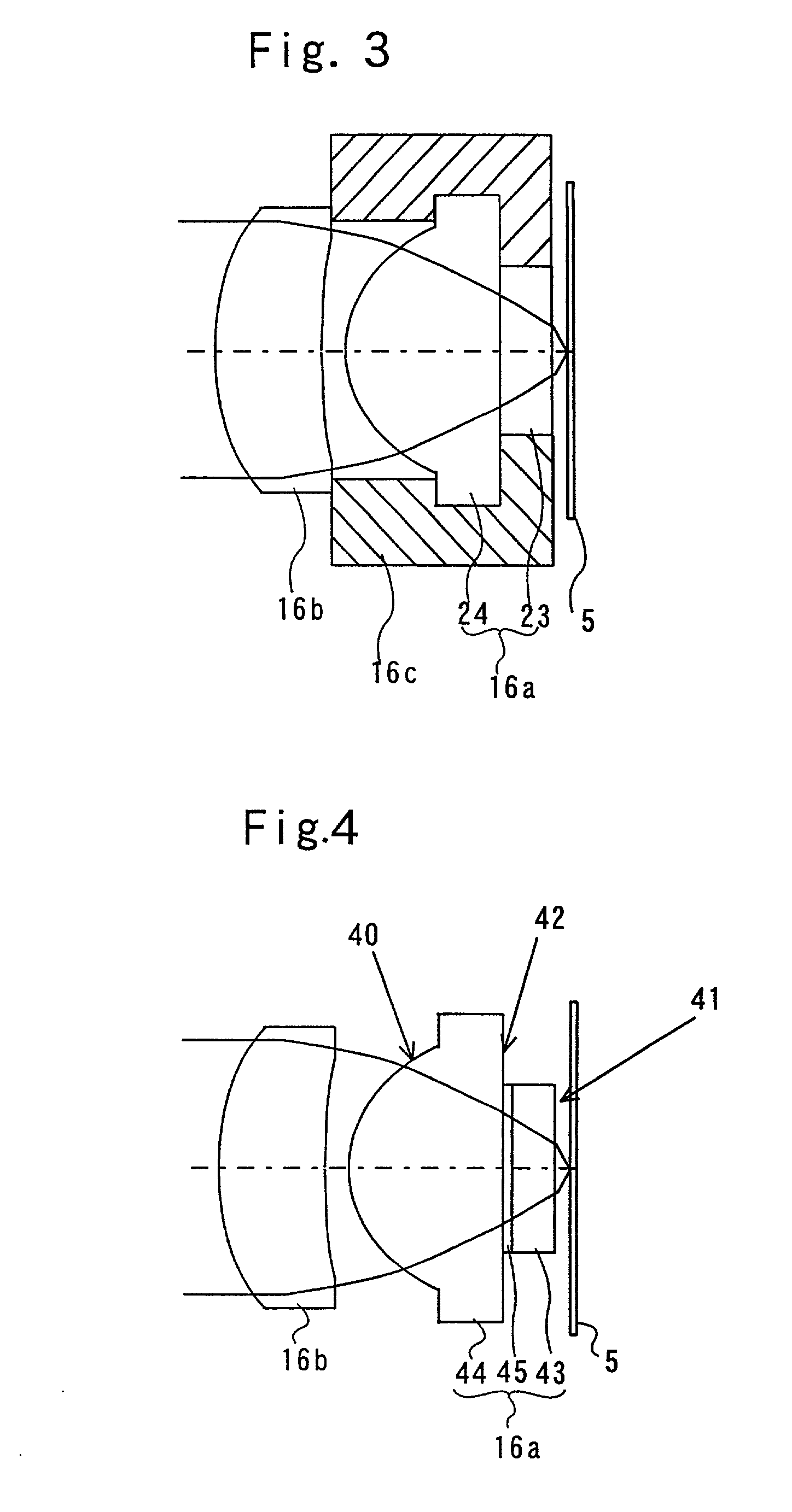
[0063] The third embodiment of the complex objective lens is similar to the first embodiment composed of the parallel flat portion and the aspherical surface portion except an intermediate film disposed therebetween. This intermediate film is an adhesive layer such as an ultraviolet curing resin for combining securely those two pieces. Moreover, the intermediate film may be formed from a multi-layer made of dielectrics to prevent from an necessary reflection at the interface. The third embodiment enables to compose the complex objective lens of two pieces without lens-barrel and to reduce stray light at the border interface due to the reflection. As shown in FIG. 4, the complex objective lens (the second lens) 16a consists of a parallel flat portion 43 or second optical element, an aspherical surface portion 44 or first optical element, and an intermediate film 45 interposed therebetween. The aspherical surface 40 at a light source side is opposite to an exit flat surface 41 at an optical disc side. The parallel flat portion 43 and the aspherical surface portion 44 are individually formed and adhered to each other at the flat face 42 via the intermediate film 45.
[0065] In addition to the features of the third embodiment, the materials of the aspherical surface portion 44, the intermediate film 45 and the parallel flat portion 43 are selected so that the refractive indexes of the portions 44, 45 and 43 increases in this order, in the fourth embodiment. Such a material selection enables to increase a tolerance of axis deviation of the first and second optical elements form the center optical axis, since a luminous flux entering through the aspherical surface portion to the parallel flat portion is refracted so as to converge into a point. As a result, the aspherical surface portion does not have to provide a large power of converging light.

Problems solved by technology

Thus, the objective lens comprising two lenses would cost more, because a process for adjusting the lenses is complicated in that assembly of the lenses is performed while the adjustment is performed by observing the condition of the lens stop on light passing therethrough.
However, it is difficult to produce the thick second lens by glass press molding.
This means that a lens having a small center radius of curvature cannot be made very thick.
This is because air existing between the inner surface of the metal mold and the preformed ball is not taken out perfectly during the press-molding if the curvature radius R of the metal mold is smaller than the diameter of the preformed ball Rf, so that an inferior molding occurs.
In such structure of a lens, however, the optical pickup would be large, which causes difficulty for an optical spot to follow a track of a recording medium such as an optical disc moving at a high speed.
According to the reasons mentioned above, in obtaining an objective lens comprising two lenses having a high numerical aperture, it is difficult to produce a stable glass pressed lens, which does not require adjustment of alignment of the two lenses and which has a small diameter and shape.
Otherwise, the image height would be insufficient when the alignment precision is relaxed, so that practical performance cannot be obtained.
This creates a difficult condition for performing a glass pressing step.
In addition, there is a problem that the maximum number of lenses formed by one metal mold is small since a metal mold is apt to be worn away over the tolerance range.
Thus, there is a problem in using the foregoing objective lens for an optical disc device to be mass-produced.
Accordingly, the volume of the second lens is limited by the limitation that the diameter of the preformed ball should not be larger than the center curvature radius of a light incident side surface of the second lens, so that a thick glass lens with a large light condensing power cannot be provided.
As a result, the objective lens must be designed under an insufficient condition of tolerance in a lens interval between the first and second lenses, so that assembly of the objective lens cannot be performed without adjustment.

Method used


Image

  • Complex objective lens and method for manufacturing the same and optical pickup device and optical recording/reproducing apparatus
  • Complex objective lens and method for manufacturing the same and optical pickup device and optical recording/reproducing apparatus
  • Complex objective lens and method for manufacturing the same and optical pickup device and optical recording/reproducing apparatus

Examples


second example

[0078] A complex objective lens of second example according to the invention will be described concretely. The wavelength of the light source used is 430 nm. The volume of the preformed glass ball is 11.0 mm.sup.3. The diameter of preformed ball is 1.38 mm. The paraxial curvature radius of the aspherical surface glass lens is 1.42 mm. The second lens volume including the flat portion is 16.5 M.sup.3. The diameter of preformed ball for the second lens volume including the flat portion is 1.58 mm. The aspherical surface shape in the second example is the same as that of the first example.

[0079] The following Tables 5 and 6 show data of respective aspherical lenses of the forgoing objective lens which are automatically designed with a computer.

5 TABLE 5 Surface Curvature Surface Refractive Number Radius Interval Index Medium 1 4.38693 1.20000 1.50497 FCD1 2 15.85658 0.20000 1.00000 Air 3 1.41642 1.70000 1.76334 M-NBF1 4 0.00000 0.60000 1.50497 FCD1 5 0.00000 0.14870 1.00000 Air 6 0.000...

first embodiment

[0081] FIG. 10 is a graph illustrating a change in wave front aberration with respect to the tolerance in a lens interval between the first and second lenses of an objective lens unit of an optical pickup in another embodiment according to the invention. The figure shows a dependence with the horizontal axis representing the lens interval tolerance and the vertical axis representing the quantity of wave front aberration (rms (.lambda.)) on the optical axis. As shown in this figure, the wave front aberration of the objective lens unit is limited to about the Marechal 's condition 0.07.lambda. in a range of lens interval tolerance larger than that of the

[0082] FIG. 11 shows a change in wave front aberration of the objective lens unit with respect to the eccentric distance of lens. In the Figure, the horizontal axis represents the distance between both the optical axes the first and second lenses (mm), and the vertical axis represents the quantity of wave front aberration (rms (.lambda...


PUM

PropertyMeasurementUnit
wavelengthaaaaaaaaaa

Abstract

A complex objective lens includes a first optical element having a first surface including a convex aspherical surface shape and an opposite side surface opposing to the first surface; and a second optical element having an exit surface through which an optical beam passing and an entry surface opposing to the exit surface. The opposite side surface opposing to the first surface of the first optical element and the entry surface opposing to the exit surface of the second optical element are directly contacted to each other.

Description

[0001] 1. Field of the Invention[0002] The present invention relates to an optical system of an optical pickup of an optical recording / reproducing apparatus for recording / reproducing information to / from an optical information recording medium such as an optical disc and an optical card and, particularly relates to an objective lens of the optical system used therein.[0003] 2. Description of the Related Art[0004] Optical discs such as a DVD (Digital Versatile Disc) are known as an optical information recording medium. A study of a high density DVD (HD-DVD) system is also in progress in order to increase the capacity of an optical disc. For the purpose of increasing density and capacity of information signals in such optical disc for writing and reading data, research and development is in progress for an optical pickup device and an information recording / reproducing apparatus with high performance.[0005] An optical beam with a short wavelength is under consideration for use for an op...

Claims


Application Information

Patent Timeline
Patent Type & Authority Applications(United States)
IPC IPC(8): G02B13/18G11B7/135G11B7/1372G11B7/1374G11B7/22
CPCG02B13/18G11B7/1374G11B7/22G11B2007/13727
Inventor KIKUCHI, IKUYAKOIKE, KATSUHIROSATO, MAKOTOMAEDA, TAKANORI
Owner PIONEER CORP
Learn More