
Nitrous oxide purification system and process

a technology of nitrous oxide and purification system, which is applied in the direction of nitrous oxides, separation processes, container discharge methods, etc., can solve the problems of inability to remove carbon dioxide impurity, potential secondary contamination source of compressors, and complex systems, etc., to achieve easy access, repair or replace, and minimize the amount of nitrous oxide lost

Inactive Publication Date: 2002-05-16
LAIR LIQUIDE SA POUR LETUDE & LEXPLOITATION DES PROCEDES GEORGES CLAUDE +1
View PDF0 Cites 8 Cited by
  • Summary
  • Abstract
  • Description
  • Claims
  • Application Information

AI Technical Summary

Benefits of technology

[0015] It is a further object of the invention to minimize the amount of nitrous oxide lost during the process.
[0016] It is another object of the invention to provide a purification system wherein the components can be easily accessed to be repaired or replaced in a quick and facile manner.

Problems solved by technology

One of the disadvantages associated with such a system is that it is far too complex, as it includes three heat exchangers and two rectification sections.
In addition, the compressor employed is potentially a secondary source of contamination due to the lubricating oils needed to operate it.
A further disadvantage associated with the system described above and other related art systems is that they are not capable of removing carbon dioxide impurity.
Carbon dioxide is known to those skilled in the purification art to be one the most difficult impurities to remove from nitrous oxide.
Additionally, although useful in removing nitrogen, oxygen and water impurities, the systems of the related art are not capable of removing other impurities such as carbon monoxide, ammonia, methane and hydrogen.

Method used


Image

  • Nitrous oxide purification system and process
  • Nitrous oxide purification system and process

Examples


example

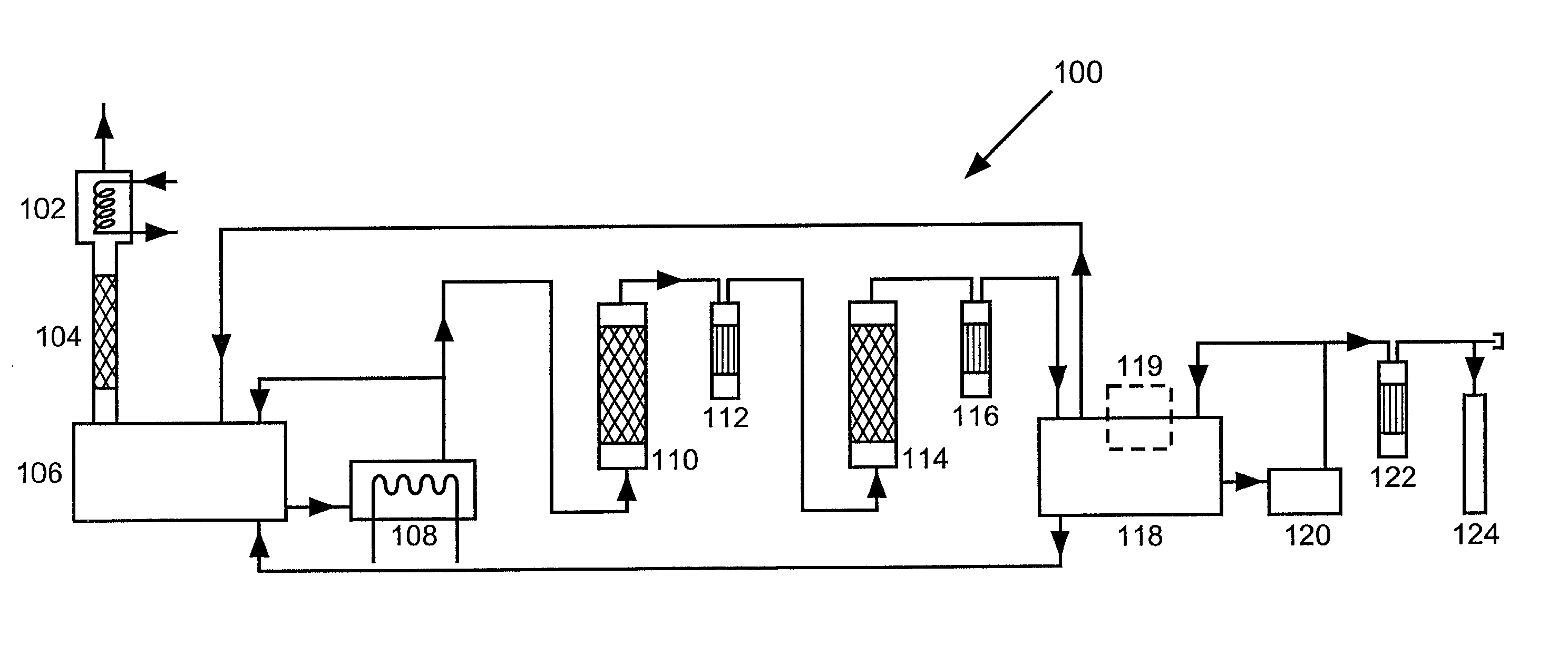
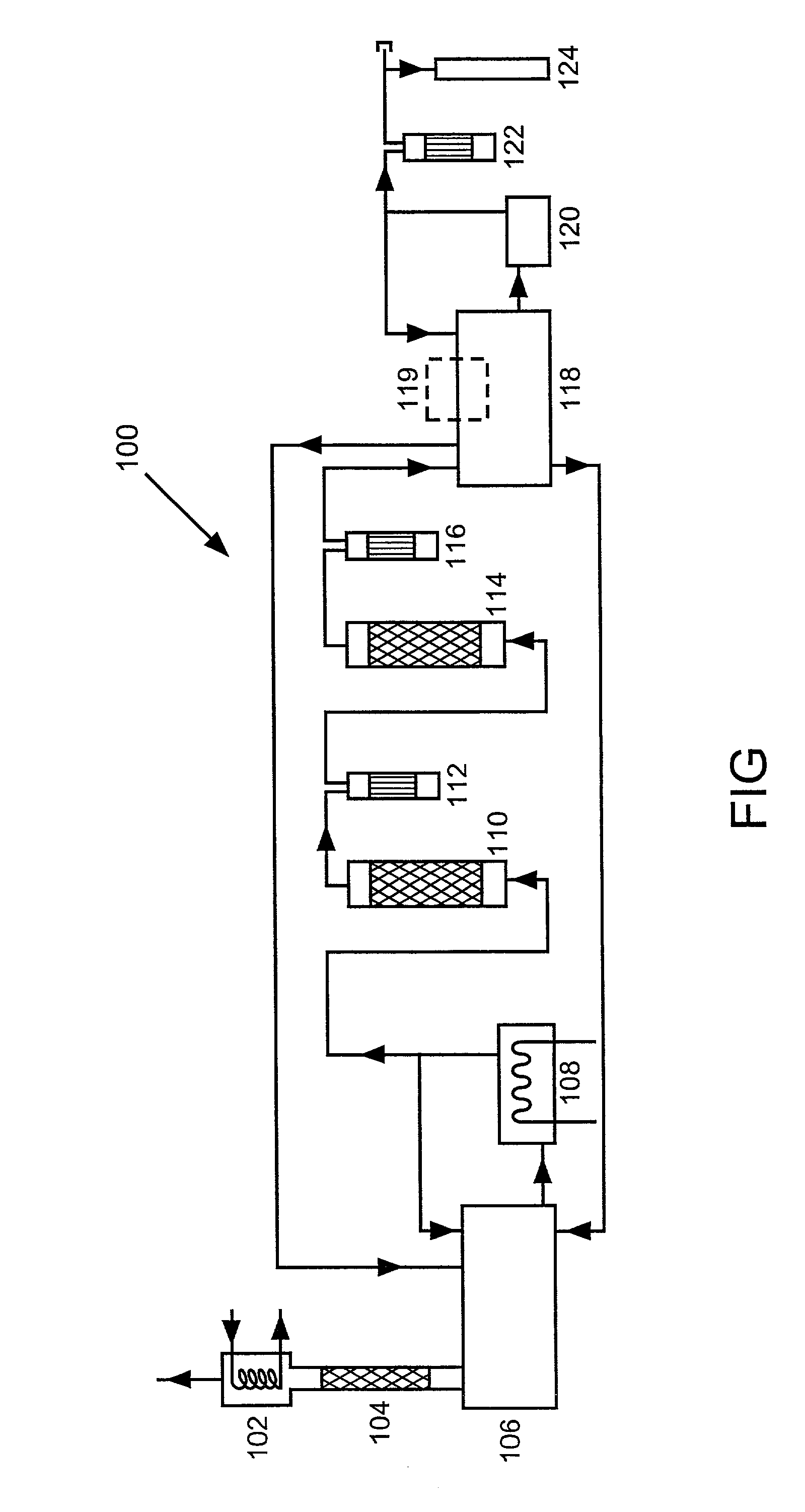
[0054] A nitrous oxide purification system as shown in the figure is pre-commission tested and thereafter thoroughly purged. At this point the system is in condition to begin nitrous oxide purification. Crude, nitrous oxide liquid (i.e., commercial grade) is pumped into a purification tank from a delivery tank truck. The purification tank employed has a maximum holding capacity of about 12,000 lb (5,454 kg) with a maximum work pressure of 350 psig (24 bar). A refrigeration system is incorporated with the purification tank where the temperature of the crude nitrous oxide liquid within the tank is maintained at between -20 and -40.degree. F. (-29 to -40.degree. C.).

[0055] From one bottom end of the purification tank, the crude liquid is routed to an external electrical vaporizer through a 1 inch (2.54 cm) 316 L stainless steel tube. The vaporization temperature is maintained at between 80 and 100.degree. F. (27 to 37.degree. C.) and the vaporization capacity ranges from 130 to 150 lb / ...


PUM


Abstract

Provided are a system and method for nitrous oxide purification, wherein the nitrous oxide product for use in semiconductor manufacturing. The system and process involve a first sub-system having a purification tank for holding a liquefied nitrous oxide, therein; a vaporizer in communication with the purification tank to receive, vaporize and convey a nitrous oxide vapor back to the purification tank; a distillation column disposed on a distal end of the purification tank to receive a nitrous oxide vapor; a condenser disposed on the distillation column, wherein light impurities are removed and wherein a nitrous oxide devoid of light impurities is conveyed and converted into vapor in said vaporizer. A second sub-system having a first dry bed vessel is disposed downstream of the vaporizer to receive the vapor and reacting the acid gas therein; a second dry bed vessel downstream of the said first dry bed vessel for removing water and ammonia in the vapor. A third sub-system having a product tank wherein the purified nitrous oxide vapor is recondensed; a transferring manifold including a liquid pump, liquid filter and a bypass for distributing the purified nitrous oxide to holding vessels.

Description

[0001] 1. Field of the Invention[0002] The present invention relates to a novel system for the purification of nitrous oxide. The present invention also relates to a method of producing nitrous oxide of ultra-high purity.[0003] 2. Description of the Related Art[0004] In the semiconductor manufacturing industry, nitrous oxide (N.sub.2O) is employed as a chemical vapor deposition (CVD) process gas for depositing films such as silicon oxide and silicon oxynitride. The use of a highly pure material is important to prevent contamination of the wafers and other deleterious effect on the processes being run ultimately resulting in degraded yield of the final product.[0005] It is particularly important that the nitrous oxide be of ultra high purity, on the order of 99.999% or greater purity. Such a purity will ensure uniform film growth during deposition.[0006] A conventional nitrous oxide purification system and process is described in European Patent Document No. 0 636 576 A1. This docume...

Claims


Application Information

Patent Timeline
IPC IPC(8): B01D3/32F25J1/00C01B21/22F25J3/02F25J3/08
CPCB01D3/322C01P2006/80C01B21/22
Inventor ZHOU, DERONGBORZIO, JOHN P.KEBBEKUS, EARLEMINER, DAVID
Owner LAIR LIQUIDE SA POUR LETUDE & LEXPLOITATION DES PROCEDES GEORGES CLAUDE
Learn More