Contact scheme for intracavity-contacted vertical-cavity surface-emitting laser

a vertical cavity and laser technology, applied in the field of contact scheme of intracavity contact vertical cavity laser, can solve the problems of poor electrical and thermal conductivity, certain limitations and drawbacks, and poor vcsel performan

Inactive Publication Date: 2002-06-13
RGT UNIV OF CALIFORNIA
View PDF3 Cites 50 Cited by
  • Summary
  • Abstract
  • Description
  • Claims
  • Application Information

AI Technical Summary

Benefits of technology

[0011] The present invention has several features combined together resulting in improved thermal characteristics as well as reduced current and optical losses. These combined features include:
[0021] Other objects of the present invention are to reduce elevated temperatures in the VCSEL, minimize optical loss associated with heavily-doped contact layers, reduce threshold current and operating voltage, and improve thermal conductivity and electrical resistivity in the VCSEL.

Problems solved by technology

While both short wavelength and long wavelength VCSELs have proven to offer excellent solutions for many applications in the evolving optical applications marketplace, they also have certain limitations and drawbacks that are well known in the art.
Some of the drawbacks are associated with the need to electrically pump as well as conduct heat through the multi-layer mirror stacks, which exhibit poor electrical and thermal conductivities.
Other drawbacks to VCSEL performance include high threshold current and high operating voltage.
Mirror stacks lattice-matched to InP, as desired for high-reliability long wavelength operation, have limited thermal conductivity, and if doped sufficiently to provide useful electrical conductivity, also create excessive optical loss.

Method used


Image

  • Contact scheme for intracavity-contacted vertical-cavity surface-emitting laser
  • Contact scheme for intracavity-contacted vertical-cavity surface-emitting laser
  • Contact scheme for intracavity-contacted vertical-cavity surface-emitting laser

Examples


Embodiment Construction

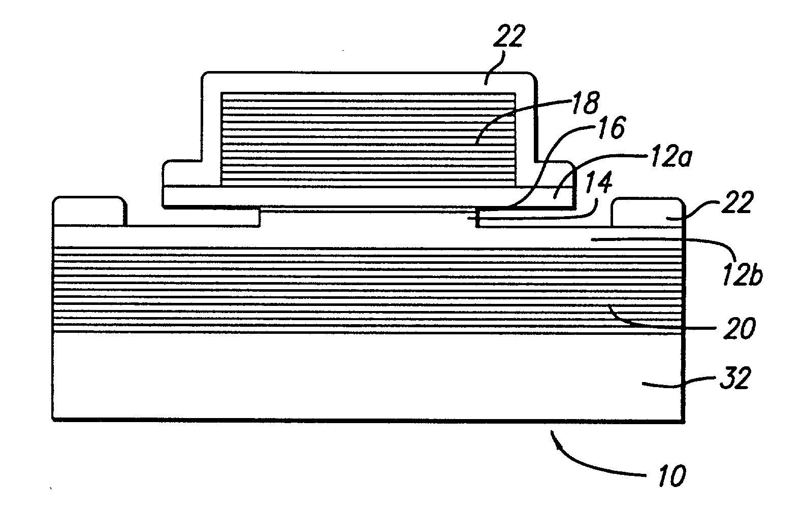
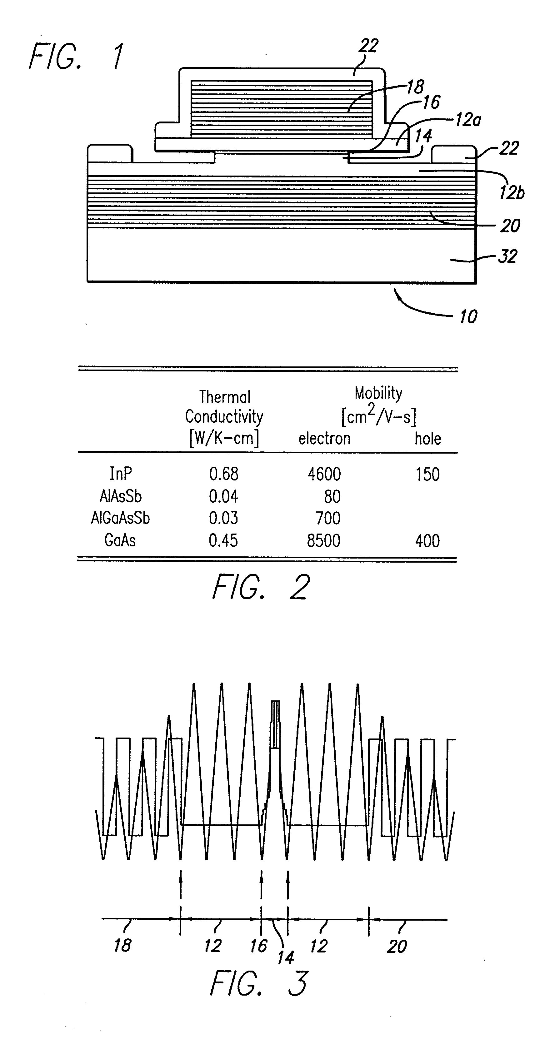
[0045] FIG. 1 is a schematic representation of a long wavelength VCSEL 10 having two InP layers 12a, 12b cladding an InAlGaAs-based active region 14, such that the active region 14 is disposed between the two InP layers 12a, 12b to form a double intracavity contacted structure. A tunnel junction 16 located between one of the InP layers 12a and the active region 14 generates holes for quantum wells in the active region 14 and allows both of the InP cladding layers 12a, 12b to be n-type. Only the InP cladding layers 12a, 12b, the tunnel junction 16 and part of the active region 14 are doped. Holes are created by the extraction of electrons from the valence band of a p-type layer in the tunnel junction 16. This design allows for the two n-type cladding layers 14 which have both higher electrical conductivity and lower optical loss than similarly-doped p-type layers. The tunnel junction 16 itself is at a standing-wave null of the cavity mode to minimize the absorption associated with th...


PUM


Abstract

A vertical cavity surface emitting laser (VCSEL) includes a semiconductor device having a pair of mirror portions, an active region, a tunnel junction, a pair of cladding layers and a substrate. Heat generated by the VCSEL dissipates through the cladding layers, which utilize an indium phosphide material. The VCSEL also includes selective etches that are used to aperture the active region to allow electric current to be injected into the active region.

Description

[0001] The contents of this application are related to those provisional applications having serial Nos. 60 / 227,165, 60 / 227,161, and 60 / 226,866, filed Aug. 22, 2000, and a provisional application having serial No. 60 / 262,541, filed Jan. 16, 2001. The present application claims priority to these related provisional patent applications and their contents are hereby incorporated by reference in their entirety into the present disclosure. The contents of this application are also related to several nonprovisional patent applications being filed concurrently herewith. These nonprovisional patent applications are hereby incorporated by reference in their entirety and have the following attorney docket reference numerals: 510015-263, 510015-264, 510015-265, 510015-266, 510015-268, 510015-269, 510015-270, 510015-271, and 510015-272.[0003] 1. Field of the Invention[0004] The invention relates in general to a vertical cavity surface emitting laser (VCSEL). More particularly, the invention rel...

Claims


Application Information

Patent Timeline
Patent Type & Authority Applications(United States)
IPC IPC(8): H01S5/024H01S5/042H01S5/183H01S5/30H01S5/323H01S5/343
CPCB82Y20/00H01S5/02461H01S5/0421H01S5/18305H01S5/18316H01S5/18341H01S5/34306H01S5/2086H01S5/305H01S5/3095H01S5/32341H01S5/3235H01S5/18344
Inventor COLDREN, LARRY A.HALL, ERIC M.NAKAGAWA, SHIGERU
Owner RGT UNIV OF CALIFORNIA
Why Eureka
Try Eureka