

Micro-multiport tubing and method for making said tubing
- Summary
- Abstract
- Description
- Claims
- Application Information
AI Technical Summary
Benefits of technology
Problems solved by technology
Method used
Image

Examples
Embodiment Construction
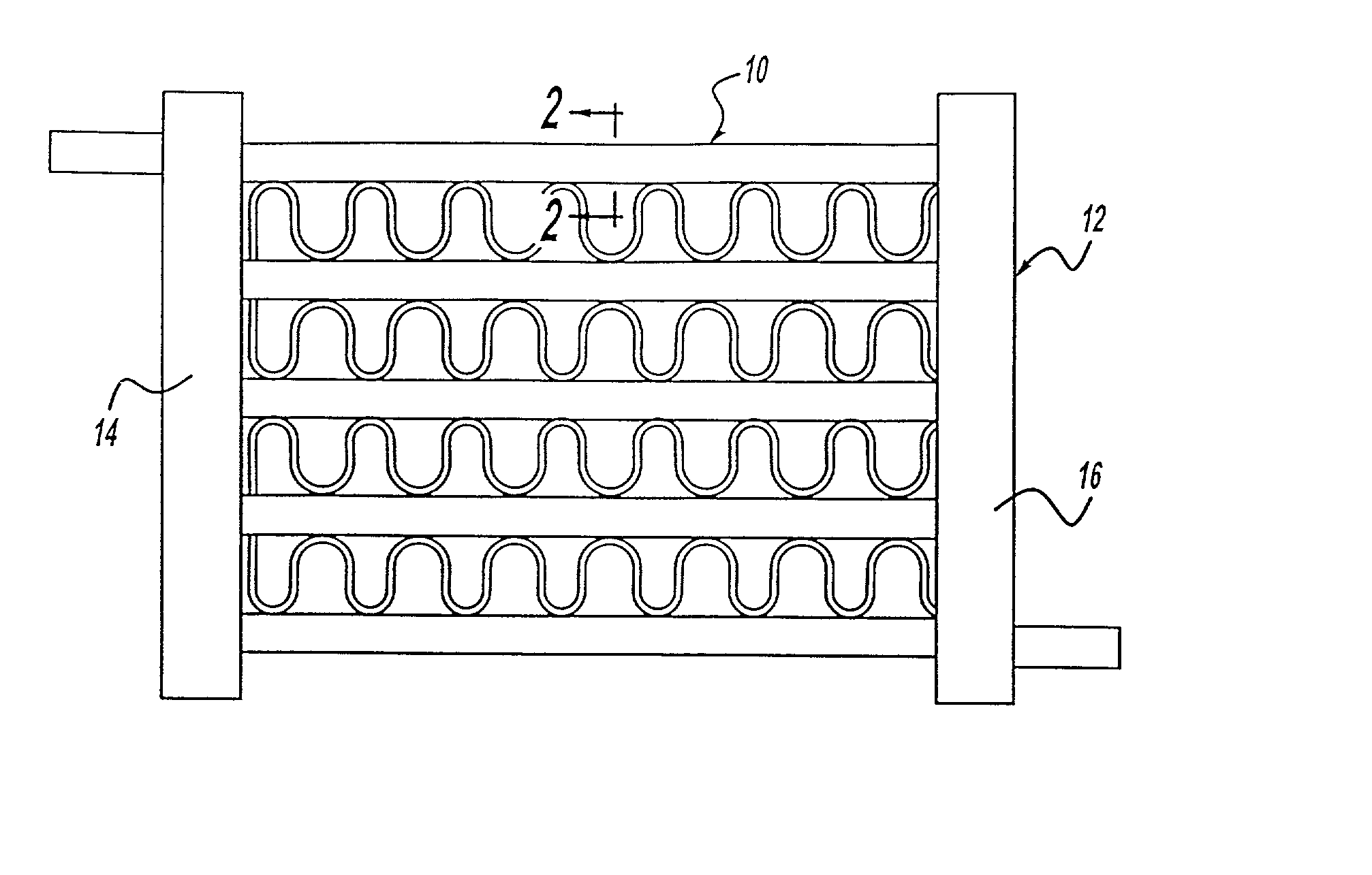
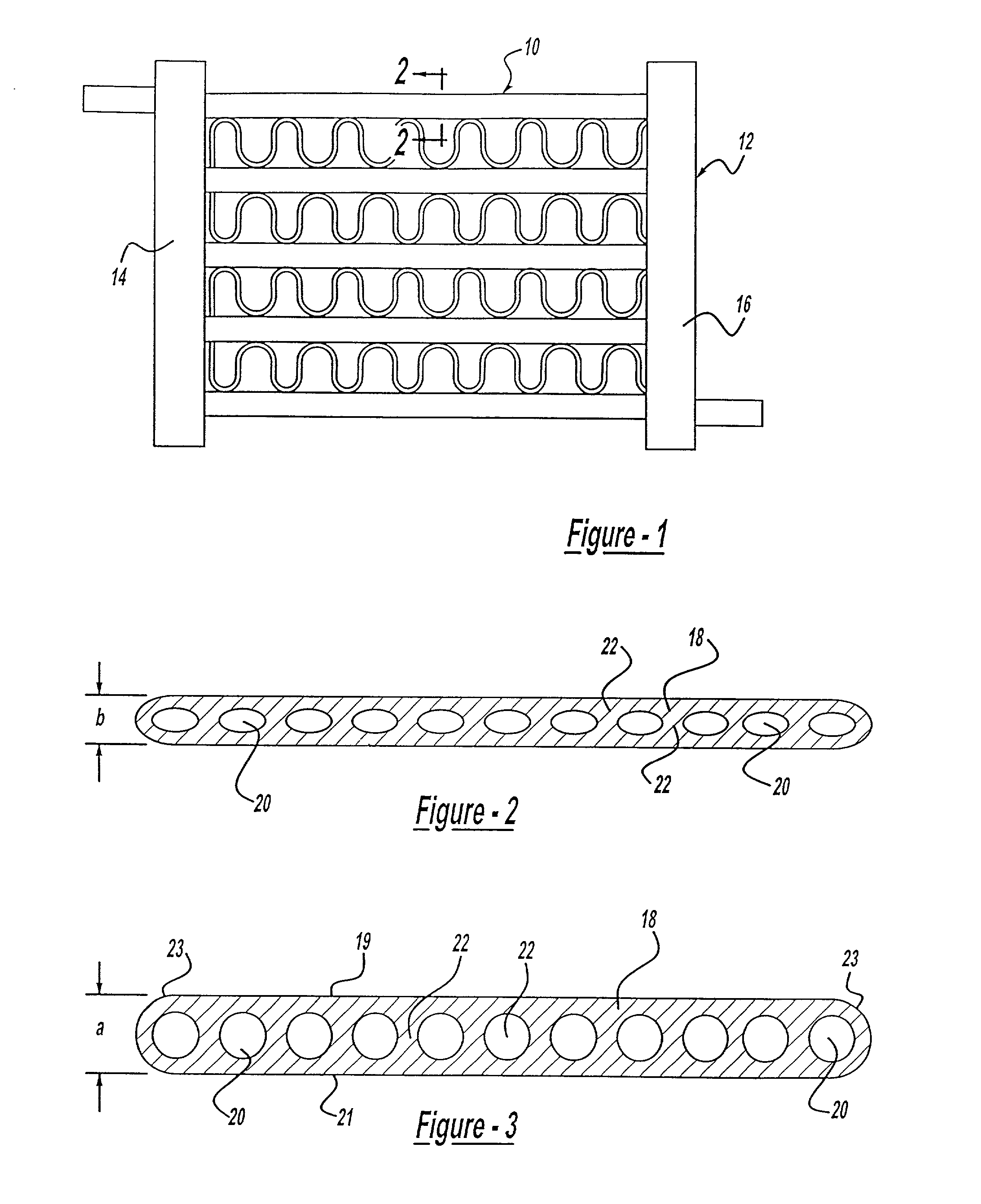
[0014] With reference to the drawing, the tubing of this invention, indicated at 10 in FIG. 1, is shown in a heat exchanger 12 with frame members 14 and 16. The tubing 10 consists of a metal body 18, which is an aluminum alloy. The body 18 is made by extrusion and the shape of the extruded body 18 is as shown in FIG. 3. The body is generally rectangular in shape having opposite faces 19 and 21 and outwardly facing rounded edges 23. A number of ports or passages 20 are arranged side-by-side between the edges 23. All of the ports 20 are of the same size and shape except for the end ports which vary only on one side.
[0015] As shown in FIG. 3, the ports 20 are defined by internal walls or webs 22, which extend in upright positions with a reduced thickness section 24 in substantially the center of the web 22. In the body 18 illustrated in FIG. 2, there are eleven ports 20 (10 webs) in side-by-side relation and each one is defined by at least one web 22. The tube 18 is of a flattened conf...
PUM
| Property | Measurement | Unit |
|---|---|---|
| Fraction | aaaaa | aaaaa |
| Fraction | aaaaa | aaaaa |
| Fraction | aaaaa | aaaaa |
Abstract
Description
Claims
Application Information