Power management for interface devices applying forces

Inactive Publication Date: 2002-09-12
IMMERSION CORPORATION
View PDF99 Cites 28 Cited by
  • Summary
  • Abstract
  • Description
  • Claims
  • Application Information

AI Technical Summary

Benefits of technology

0011] The present invention is directed to implementations of a human/computer interface device for controlling and providing force feedback to a user. Several implementat

Problems solved by technology

This is because most of the force feedback devices have been targeted at the specific needs of highly industrial or scientific applications, and not a mass consumer market.
As a result, typical force feedback interface devices include complex robotic mechanisms which require precise, bulky, and expensive components that have significant power requirements and are difficult to program for applications.
A problem is evident when prior art force feedback interface devices are provided to the mass consumer market.
However, these standard serial communication interfaces are typically quite slow (i.e. have low bandwidth) compared to other communication interfaces.
Realistic and accurate force

Method used


Image

  • Power management for interface devices applying forces
  • Power management for interface devices applying forces
  • Power management for interface devices applying forces

Examples


embodiment 50

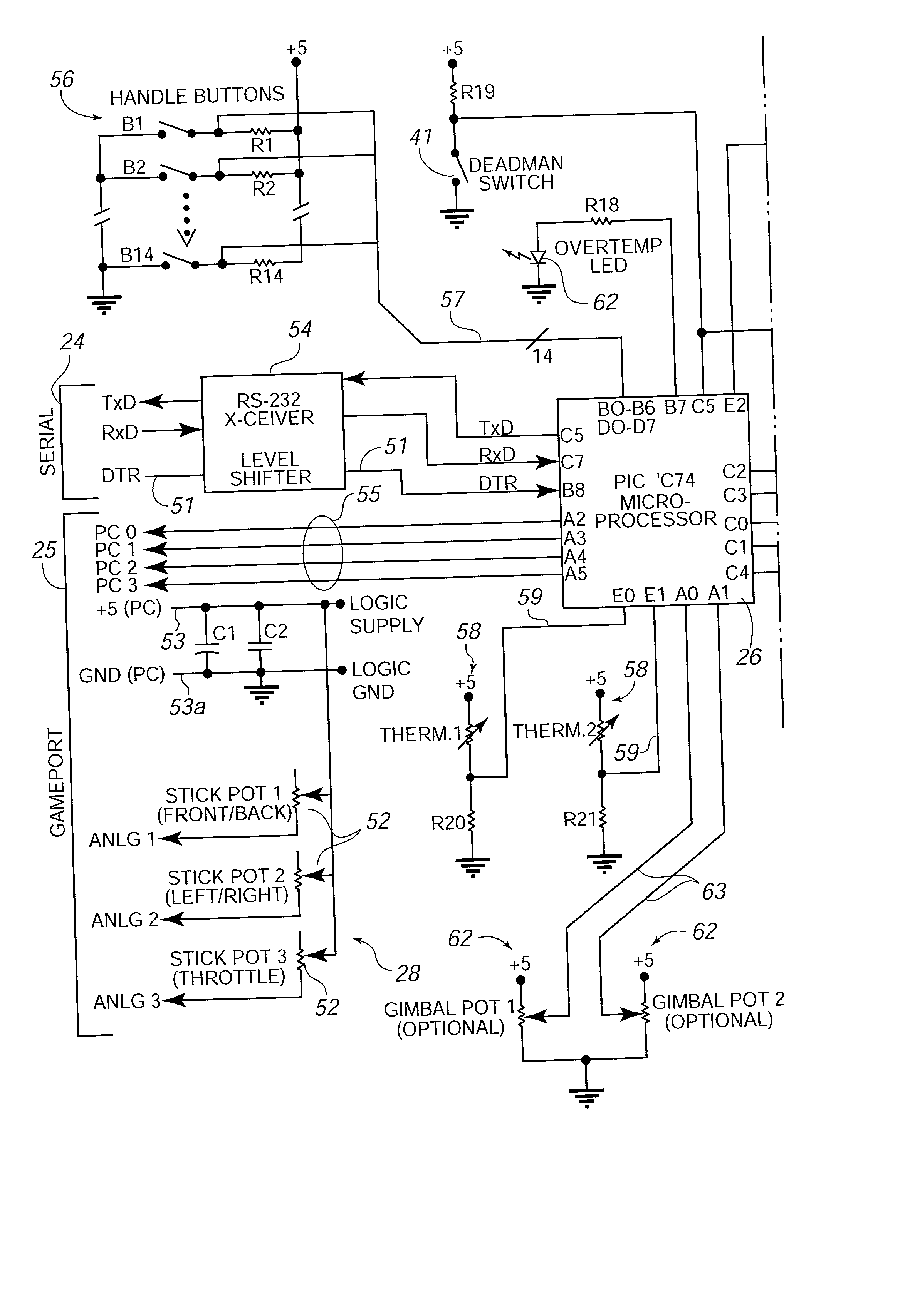
[0074] FIG. 3 is a schematic diagram of an example of a specific embodiment 50 of the interface device 14. Local microprocessor 26, in this example, is a PIC16C74 available from Microchip and having 14 address lines and 8 data lines. This microprocessor includes an internal architecture that splits memory into two partitions and allows fast program executions, and is thus well-suited for high speed force feedback processing. This embodiment preferably includes local memory 27, such as ROM, as well as local clock 29 on board the microprocessor.

[0075] Interface device 50 is intended to communicate with host computer 12, as explained with reference to FIG. 2, using both a serial interface such as an RS- 232 interface as well as a second interface 25, which, in the described embodiment, a game port interface as typically found on an MBM-compatible personal computer (PC).

[0076] Sensors 28 are used to sense the position of user object 34 in provided degrees of freedom. In the described em...

embodiment 80

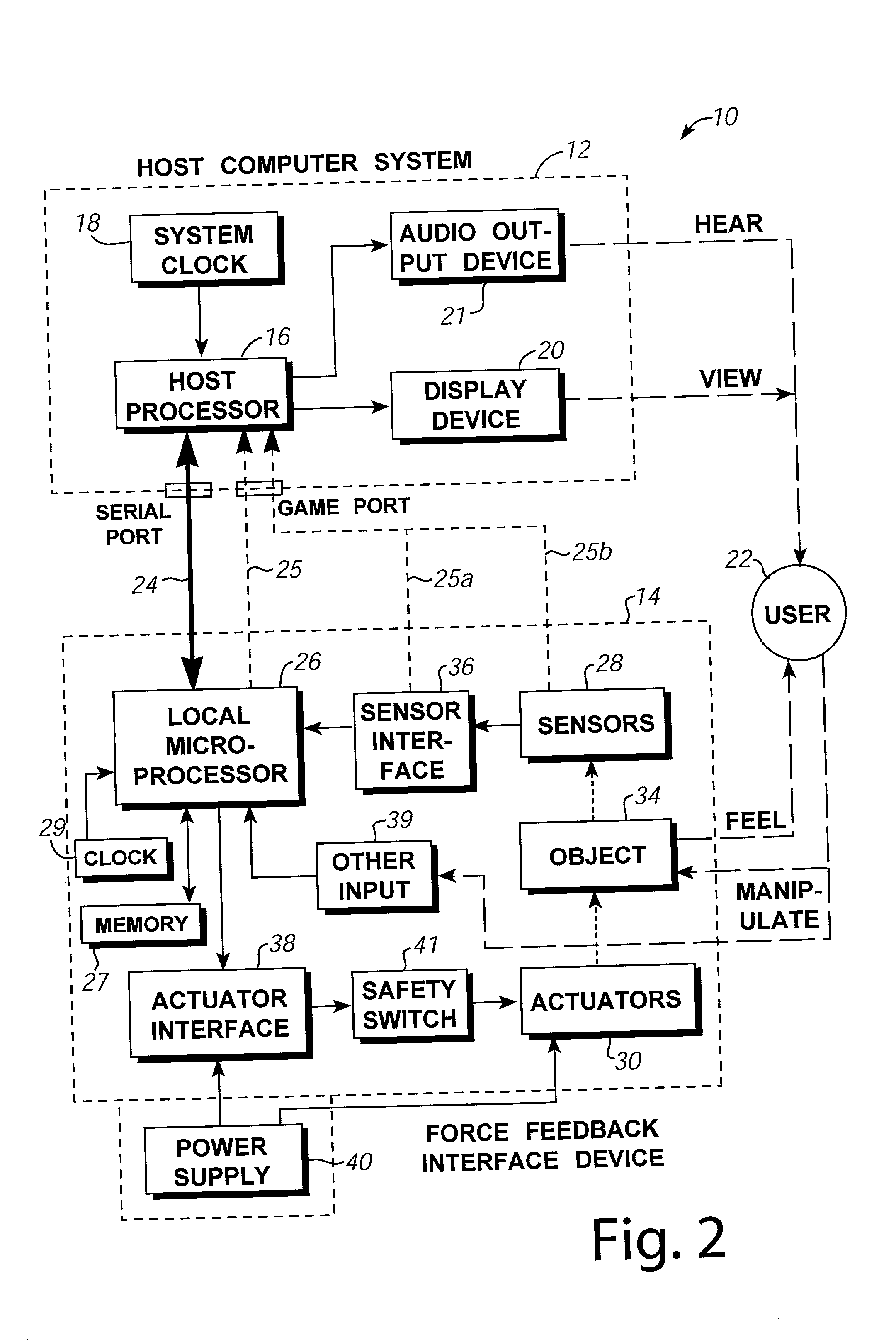
[0095] FIG. 4a is a block diagram of an alternate "recoil" embodiment 80 of the force feedback control system 10 of FIG. 2. In recoil control system 80, a local device microprocessor 26 is not necessary to provide force feedback and the host computer sends no signals, or only minimal signals, to the interface device 14. The recoil embodiment is thus a "reflex" interface device, in that forces are output on user object 34 independently of host computer 12, and these forces depend only on local control events (e.g. a press of a button by the user). The reflex process includes outputting a force when a button is pressed with no communication from the host.

[0096] The position of user object 34 is sensed by sensors 28, and the sensors send position or other related signals to the host computer 12. The control loop includes buttons or other input devices 39, which sense actions of the user such as when the user pushes one of the buttons. The buttons 39 provide input signals to a recoil re...

embodiment 130

[0139] the interface device has several advantages. Since no local microprocessor 26 or UART are needed in interface device 130, the cost of the interface device is reduced greatly. The implementation of a serial data stream allows the host to send a greater number of control signals and have much greater control than in the embodiments of FIGS. 4a-4f. Many more types of commands can be sent by the host using the serial interface than the three maximum commands allowed in the parallel bus implementation of an RS-232 interface in the above "recoil" embodiments. Also, force values or other commands can be sent by the host to better control the actuators. In addition, the logic components of interface device 130 shown in FIG. 5 can be readily provided on a single chip implemented as an ASIC or FPGA. This allows the circuitry for interface device 130 to be manufactured in high volume at a very low cost.

[0140] FIG. 6 is a schematic diagram illustrating a low-cost and compact power circui...


PUM


Abstract

A method and apparatus for providing safe and low-cost force feedback peripherals for consumer applications. A device microprocessor local to an interface device is coupled to the host by a first interface bus. The microprocessor receives host commands from the host computer on the first interface bus, such as an RS-232 interface, and commands an actuator to apply a force to a user object, such as a joystick, in response to host commands. A sensor detects positions of the user object and outputs signals to the host on a second interface bus, such as a PC game port bus, separate from the first bus. In a "recoil" embodiment, a user initiates force feedback by pressing a button on the joystick, which sends an activation signal to the actuator. In other recoil embodiments, the host computer can transmit one or more enable signals and/or activation signals to the actuator to enable or command forces. A safety switch of the present invention disables the actuator when the interface device is not in use and enables the actuator when an amount of weight over a predetermined amount is placed on the joystick created by a user grasping the joystick. A circuit of the present invention includes a capacitor for storing power provided by an input signal and supplied to the actuator when forces are to be output.

Description

CROSS REFERENCE TO RELATED APPLICATIONS[0001] This application is a continuation-in-part of co-pending parent patent application Ser. No. 08 / 534,791, filed Sep. 9, 1995 on behalf of Louis B. Rosenberg, entitled, "Method and Apparatus for Controlling Human-Computer Interface Systems Providing Force Feedback", and co-pending parent patent application Ser. No. 08 / 566,282, filed Dec. 12, 1995 on behalf of Louis B. Rosenberg et al., entitled, "Method and Apparatus for Controlling Force Feedback Interface Systems Utilizing a Host Computer," both assigned to the assignee of this present application, and both of which are hereby incorporated by reference herein.BACKGROUND OF THE INVENTION[0002] The present invention relates generally to interface devices between humans and computers, and more particularly to computer interface devices that provide force feedback to the user.[0003] Computer systems are used extensively in many different industries to implement computer controlled simulations...

Claims


Application Information

Patent Timeline
IPC IPC(8): A63F13/06G05G9/047G06F1/26G06F3/00G06F3/01G06F3/038H04L29/06
CPCG06F2203/015H01H2003/008A63F13/06A63F2300/1025A63F2300/1031A63F2300/1037G05G9/047G05G2009/04766G05G2009/04777G06F1/266G06F3/011G06F3/016G06F3/0383G06F2203/014H04L67/38A63F13/23A63F13/285H04L67/131A63F13/57A63F2300/8017A63F2300/64A63F2300/8082A63F13/21A63F13/803A63F13/235
Inventor ROSENBERG, LOUIS B.BRAUN, ADAM C.SCHENA, BRUCE M.
Owner IMMERSION CORPORATION
Why Eureka
Try Eureka