Process for the production of hydrogen peroxide solution

a hydrogen peroxide and hydrogen peroxide technology, applied in the direction of peroxide/peroxyhydrate/peroxyacid/superoxide/ozonide, chemistry apparatus and processes, etc., can solve the problems of large environmental damage, hydrogen peroxide is too unstable to store, and the effect of avoiding the production of effective chlorine or thm

Inactive Publication Date: 2002-09-19
DE NORA PERMELEC LTD +1
View PDF0 Cites 6 Cited by
  • Summary
  • Abstract
  • Description
  • Claims
  • Application Information

AI Technical Summary

Benefits of technology

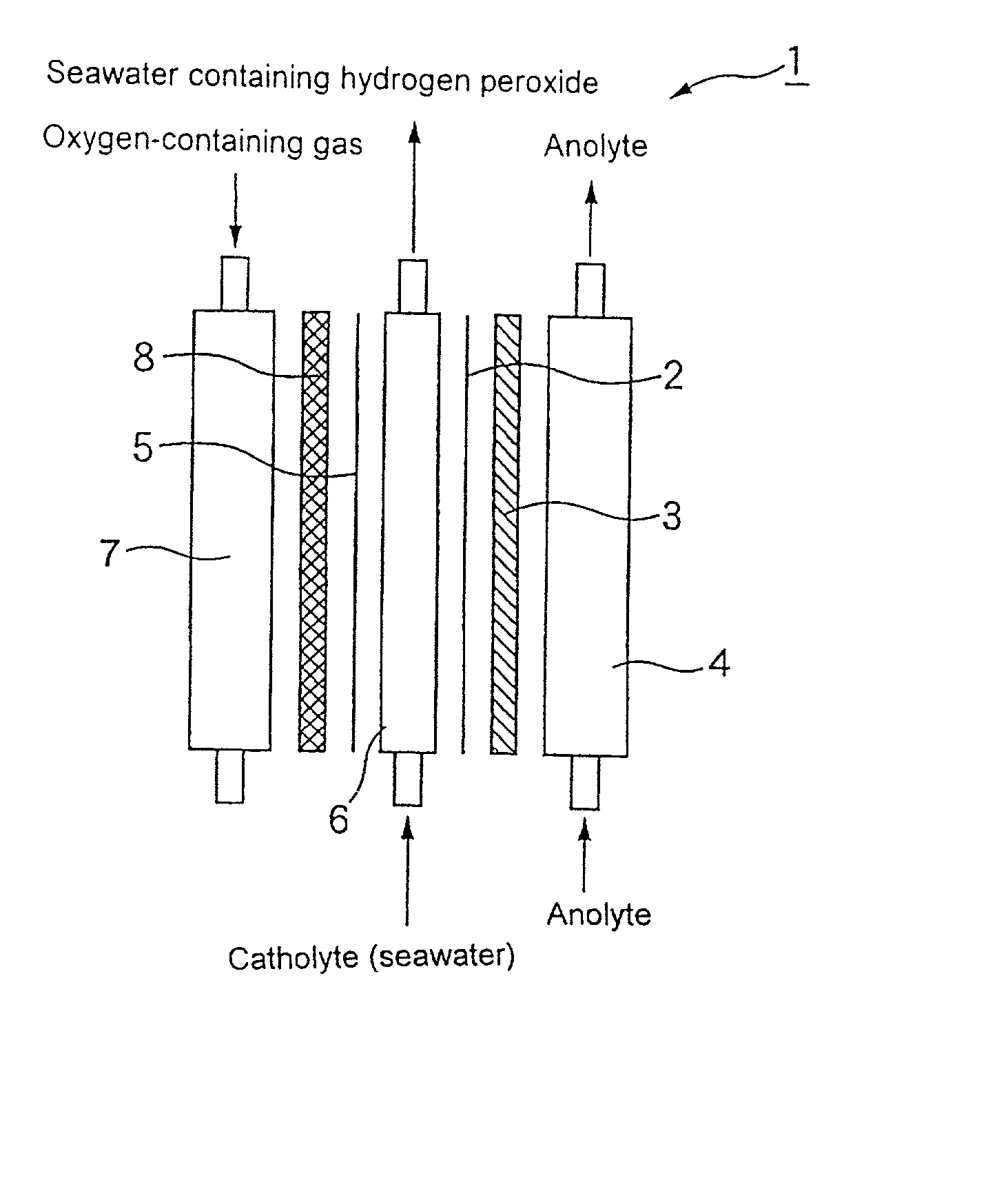
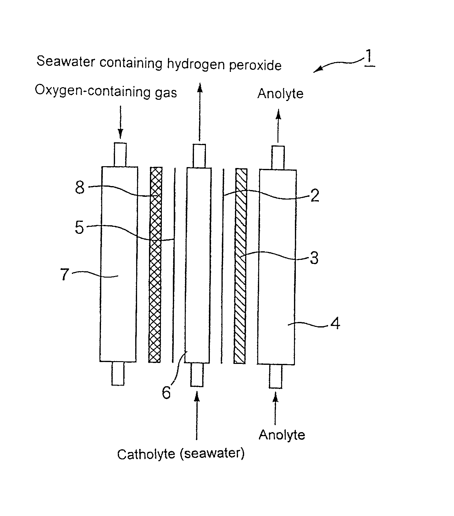
[0015] It is therefore an object of the invention to provide a process for the production of a hydrogen peroxide solution using a solution having a low halide ion concentration as an anolyte for the production of seawater containing hydrogen peroxide by the electrolysis of seawater. The process of the invention practically avoids the production of effective chlorine or THM, which is unavoidable in conventional processes for the production of hydrogen peroxide solution from seawater.

Problems solved by technology

Due to concern that the pollution and the deterioration of water quality of rivers and lakes caused by industrial and household wastes can have adverse effects on the environment and human body, technical countermeasures for solving these problems are urgently needed.
Further, under some combustion conditions, the incineration of waste can cause the production of carcinogenic substances (dioxins) which affect the ecosystem and thus has been noted as a safety problem.
However, when hypochlorous acid is discharged untreated, it decomposes to produce organic chlorine compounds and chlorine gas, which are considerably harmful to the environment.
However, hydrogen peroxide is too unstable to store over an extended period of time.
However, this method has a low current efficiency and thus is not practical.
However, this proposal, too, is not practical from the standpoint of safety.
However, this electrolysis process is limited in its use because it can produce hydrogen peroxide only in a low concentration and adds to cost.
Even when an electrode which resists the generation of chlorine gas or the like is used or when a cation exchange membrane is used to separate the cathode from the anode, which is a site for the production of chlorine gas, the oxidation of chloride ions or the like cannot be completely prevented.
Further, chlorine gas or the like is likely to react with organic compounds in the seawater to produce a harmful trihalomethane (THM).
However, this method requires the installation of a hydrogen gas anode and the supply of hydrogen gas, adding to cost.
Thus, this method is not economical.
Further, this method involves a danger in handling hydrogen gas.
However, because seawater containing a large amount of organic compounds is used as an anolyte, the production of THM is unavoidable.
As discussed above, when seawater containing an organic compound and halide ions is subjected to electrolysis in a conventional manner to produce seawater containing hydrogen peroxide, the production of organic halogen compounds such as THM unavoidably occurs, raising a great environmental and hygienic problem.

Method used


Image

  • Process for the production of hydrogen peroxide solution
  • Process for the production of hydrogen peroxide solution

Examples


example 1

[0050] An iridium oxide catalyst was supported on a porous titanium sheet in an amount of 10 g / m.sup.2 by a thermal decomposition method to prepare an anode.

[0051] A carbon powder (Type XC-72 furnace black, produced by Vulcan Inc. of U.S.A.) as a catalyst was kneaded with a PTFE resin. The mixture was applied to a carbon cloth (produced by Nippon Carbon Co., Ltd.), and then calcined at a temperature of 330.degree. C. to prepare a sheet having a thickness of 0.4 mm as an oxygen gas electrode.

[0052] The foregoing anode was placed in close contact with an ion exchange membrane (Nafion 117, produced by Du Pont Inc.). The foregoing oxygen gas electrode was arranged such that the distance between the oxygen gas electrode and the anode electrode was 5 mm. As a result, an electrolytic cell shown in FIG. 1 having an effective electrolysis area of 150 cm.sup.2 and comprising an anode chamber and a cathode chamber (solution chamber and gas chamber) was assembled.

[0053] An electric current of 1...

example 2

[0056] An electrolytic cell was assembled in the same manner as in Example 1, except that an anode obtained by subjecting a porous titanium sheet to electrodeposition in an acidic aqueous solution of manganese sulfate to support a manganese dioxide catalyst thereon in an amount of 50 g / m.sup.2 was used. Electrolysis was effected using this electrolytic cell.

[0057] Seawater having a hydrogen peroxide content of 1,000 ppm was obtained at the outlet of the solution chamber at a current efficiency of about 95%. The effective chlorine concentration of tap water at the outlet of the anode chamber was not greater than 1 ppm. At this point, the concentration of THM at the outlet of the solution chamber fell below the limit of detection.

example 3

[0058] An electrolytic cell was assembled in the same manner as in Example 1, except that as the anolyte supplied to the anode chamber was industrial water having a chloride ion concentration of 20 ppm and TOC of 2 ppm. Electrolysis was effected using this electrolytic cell.

[0059] Seawater having a hydrogen peroxide content of 1,000 ppm was obtained at the outlet of the solution chamber at a current efficiency of about 95%. The effective chlorine concentration of tap water at the outlet of the anode chamber was not greater than 50 ppm. The cell voltage was 7.5 V. At this point, the concentration of THM at the outlet of the solution chamber fell below the limit of detection.


PUM

PropertyMeasurementUnit
concentrationaaaaaaaaaa

Abstract

A process for the production of hydrogen peroxide solution from seawater as a starting material substantially free of effective chlorine or organic halogen compounds. An electric current is passed through an insoluble anode and an oxygen gas diffusion cathode while keeping the halide ion concentration of anolyte supplied to the anode chamber to a level not greater than 1 g / l. Hydrogen peroxide thus generated dissolves in the catholyte. Anodic oxidation of halide ions is suppressed, to thereby inhibit the production of effective chlorine.

Description

FIELD OF THE INVENTION[0001] The present invention relates to a process for the production of a hydrogen peroxide solution which includes electrolyzing seawater to produce hydrogen peroxide with secondary production of effective chlorine or organic halogen compound in a minimized amount.BACKGROUND OF THE INVENTION[0002] Due to concern that the pollution and the deterioration of water quality of rivers and lakes caused by industrial and household wastes can have adverse effects on the environment and human body, technical countermeasures for solving these problems are urgently needed. In the treatment of drinking water, sewage and waste water, the practice has been to add a chemical such as chlorine to decolor and sterilize the water to be treated and reduce the COD thereof. However, since the addition of a large amount of chlorine causes the production of harmful materials, i.e., environmental hormones (extrinsic incretion disturbing material) and carcinogenic substances, the recent...

Claims


Application Information

Patent Timeline
Patent Type & Authority Applications(United States)
IPC IPC(8): C25B1/30C01B15/027C25B9/19
CPCC25B1/30
Inventor NAKAJIMA, YASUONISHIKI, YOSHINORIUNO, MASAHARUKATSUMOTO, AKIRANISHIMURA, KUNIO
Owner DE NORA PERMELEC LTD
Why Eureka
Try Eureka