Multilayered polymeric structure

a polymer and polymer technology, applied in the field of multi-layered polymer structure, can solve the problems of static charge affecting the quality of signals carried in cables, the component is not protected from electric charge originating outside of the tray or package, and the current flow through the component far exceeding its current carrying capacity

Inactive Publication Date: 2002-09-19
HYPERION CATALYSIS INT
View PDF0 Cites 8 Cited by
  • Summary
  • Abstract
  • Description
  • Claims
  • Application Information

AI Technical Summary

Benefits of technology

[0024] It is therefore an object of the invention to provide an improved packaging material which will protect sensitive electric components from damage or destruction due to electrostatic discharge.
[0026] It is a further object of the invention to provide improved shielding for signal carrying cables.
[0032] An advantage of having the outer layer of the multilayered material more conductive than the inside antistatic layer is that the outer layer acts as a shunt for any electric current originating outside of a tray or package made of the material. Should a source of electric charge come in contact with the outside surface of a tray or package made of the multilayered material, the outer layer will conduct the current to a point on the outer surface where the current may leave the material. The relatively higher resistance of the inner antistatic layer impedes current flow through that layer and into components which may be present on the other side.
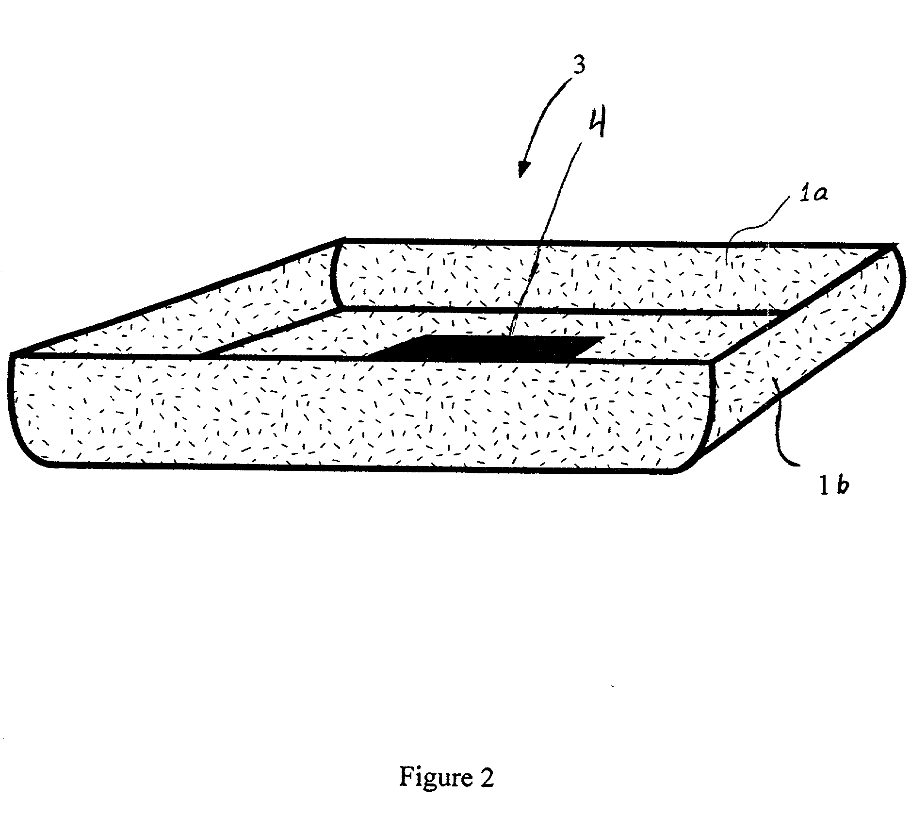
[0049] FIG. 2 shows a tray 3 made from the multilayered material of this invention. The first layer 1a of the material forms the inside antistatic surface of the tray 3. A carbon fibril concentration of 2.5% by weight provides the inside layer with a surface resistance of about 1.times.10.sup.7 ohms per square. The high level of surface resistance of the inside layer la allows for the slow dissipation of any electrostatic charge which may build on components present inside the tray 3. This charge is dissipated through the outer layer 1b which is in electrical contact with the inner layer 1a.
[0050] The second layer 1b forms the outside surface of the tray 3 and has a surface resistance of about 1.times.10.sup.4 ohms per square. The second layer contains about 5% by weight of carbon fibrils, and due to the lower resistance of layer 1b relative to 1a, layer 1b reduces the risk of electrical charge flowing from outside the tray into the tray and damaging components therein. Layer 1b acts as a shunt guiding current away from the sensitive components inside the tray. Item 4 in FIG. 2 represents an electrical component which can be carried by using tray 3.

Problems solved by technology

The sudden discharge of static electricity which may build on a sensitive electrical component often results in current flow through the component far exceeding its current carrying capacity.
Static charges can also impact the quality of signals carried in cables.
Although prior art packages and trays made of polymeric material are suitable for dissipating electric charge from sensitive components, they do not protect the components from electric charge originating outside of the tray or package.
If a conventional tray or package of the prior art comes in contact with a current source having sufficiently high voltage, electric current can flow through the tray or package, and through the components therein, damaging the components.
Trays and packages made from the single layer polymeric materials of the prior art provide no means for shunting current away from the components, and therefor are not suitable for protecting components against charge emanating outside the tray or package.
Further, the effectiveness of single layer materials of the prior art may be limited to specific ranges of voltage or frequency.
The differences make graphite and carbon black poor predictors of nanotube chemistry.

Method used


Image

  • Multilayered polymeric structure
  • Multilayered polymeric structure
  • Multilayered polymeric structure

Examples


examples 1-9

[0053] Masterbatch compositions containing 15% fibril loading were prepared according to methods described in the examples section of U.S. Pat. No. 5,651,922 to Nahass et al. incorporated herein by reference. Masterbatch formulations were prepared having 15% by weight carbon fibrils obtained from bird's nest (BN) aggregates and 85% polyethylene terephtalate modified with cylcohexanedimethanol (PETG). Other masterbatch compositions included 15% by weight carbon fibrils from bird's nest type aggregates and 85% polybutylene terephtalate (PBT). Yet other masterbatch composition were prepared to include 15% by weight carbon fibrils from bird's nest type aggregates and 0.5% by weight polytetrafluoroethylene (PTFE) and the balance PETG.

[0054] The above masterbatch compositions were used to make other formulations as listed in Table 1 below. For example, to make a PETG / SBN product 33.5% PBT / 15BN was mixed with 66.7% PETG polymer. PBT and PETG trans-esterify to form a hybrid mixture of two p...


PUM

PropertyMeasurementUnit
diameteraaaaaaaaaa
aspect ratiosaaaaaaaaaa

Abstract

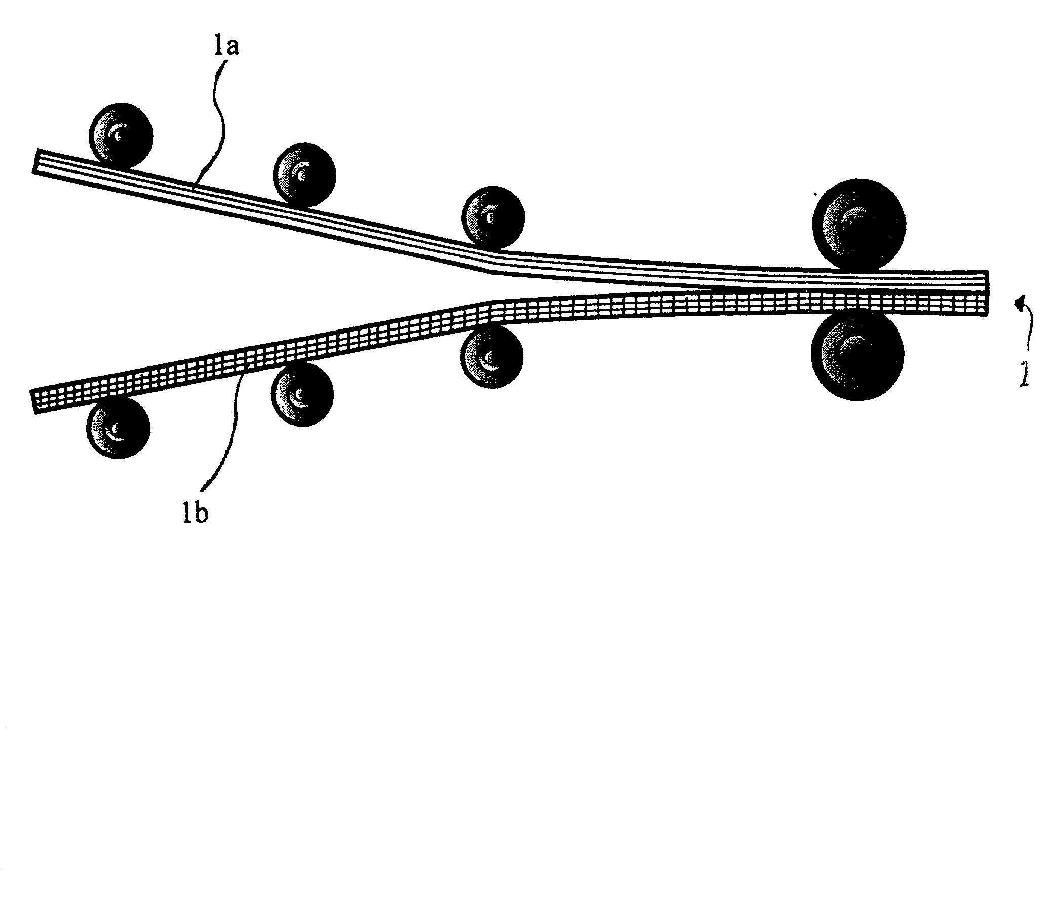
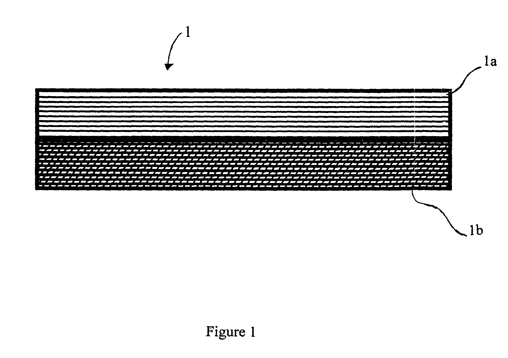
A multilayered polymeric structure having at least two polymeric layers is provided, each layer being a mixture of a polymeric composition with carbon fibrils. The multilayer polymeric structure may include an electrically conductive material between the first and second polymeric layers. A process for making a multilayered polymeric structure for packaging electronic components is also provided. The multilayered polymeric material is used to form trays and packages for containing electrical components.

Description

[0001] This application is a continuation in part of Ser. No. 09 / 593,781 filed Jun. 14, 2000, which is incorporated by reference herein in its entirety.[0002] 1. Field of Invention[0003] The invention relates generally to electrically conductive polymers and more particularly to antistatic and electrically protective packaging made of multilayered polymeric materials.[0004] 2. Description of the Related Art[0005] Antistatic materials[0006] The sudden discharge of static electricity which may build on a sensitive electrical component often results in current flow through the component far exceeding its current carrying capacity. In order to protect and avoid the damage or destruction of such components, slow dissipation of the static charge from these components is crucial. For this reason, static-sensitive components are typically transported and stored on trays or in containers made of "antistatic" material having a very high resistance. The high resistance of the material allows e...

Claims


Application Information

Patent Timeline
Patent Type & Authority Applications(United States)
IPC IPC(8): B65D1/00B32B7/02B32B27/18B32B27/20B32B27/36B65D65/40B65D85/86C08K3/04C08L101/00H01B1/24H05K9/00
CPCB29C45/0005B29C45/16B29C47/0019B29C47/0021B29C47/0047B29C47/065B29C70/882B29K2995/0005B32B27/08B32B27/18B32B27/20B32B27/322B32B27/36B32B2250/24B32B2262/106B32B2307/20B32B2307/21B32B2439/00B32B2553/00B65D2585/86H01B1/24H01L23/145H05K9/0067H05K9/0088H05K9/009H01L2924/0002H01L2924/00Y10T428/1352Y10T428/24942Y10T156/10B29C48/0014B29C48/07B29C48/08B29C48/21
Inventor FRIEND, STEPHEN O.BRYANT, EDWARD W.S.FOWLER, HAROLD C.
Owner HYPERION CATALYSIS INT
Why Eureka
Try Eureka