Automotive four-cycle engine

a four-cycle engine and engine technology, applied in the direction of machines/engines, output power, electric control, etc., can solve the problems of difficult recirculation of exhaust gas in higher-load conditions, shortening the intake period of each cylinder, and affecting the performance of the engine, so as to avoid the increase in combustion temperature, increase the engine output, and improve the effect of anti-knocking performan

Inactive Publication Date: 2002-11-14
MAZDA MOTOR CORP
View PDF0 Cites 40 Cited by
  • Summary
  • Abstract
  • Description
  • Claims
  • Application Information

AI Technical Summary

Benefits of technology

0021] In this construction, the internal EGR is accomplished and increases in combustion temperature and exhaust gas temperature are avoided in the maximum-load region even in the medium- to high-speed ranges of the engine and, yet, a sufficient amount of fresh air is drawn in by turbocharging while the internal EGR is being executed. In particular, anti-knocking performance of the engine is increased since the increase in combustion temperature is avoided. As a result, it becomes possible to increase the engine output by turbocharging, a feature which has conventionally been unachievable due to knocking.
0022] It is preferable for the automotive four-cycle engine provided with the turbocharger to further comprise an air-fuel ration controller for controlling the air-fuel ratio of a mixture in a combustion chamber and thereby make the air-fuel ratio equal to or larger than the stoichiometric air-fuel ratio in the maximum-load region in the medium-to high-speed ranges of the engine. Since this arrangement increases the anti-knocking performance of the engine by setting the closing point of the exhaust valve to a point before the intake top dead center in the maximum-load region in the medium- to high-speed ranges of the engine as described above, it becomes unnecessary to enrich the mixture for preventing knocking combustion. Thus, both engine output performance and fuel efficiency can be improved by increasing the air-fuel ratio up to the stoichiometric air-fuel ratio while introducing a sufficient amount of fresh air by turbocharging.

Problems solved by technology

While a specified portion of exhaust emissions is returned to an intake passage on a downstream side of downstream of a throttle valve and re-introduced into the combustion chamber in the engine provided with the external EGR system, it is difficult to recirculate a sufficient amount of exhaust gas under higher-load conditions in a high-speed range, because negative pressure in the intake passage decreases on the downstream side of the throttle valve and an intake period of each cylinder shortens under high-speed high-load conditions.
In addition, the external EGR system is associated with a problem that exhaust gas deposits are likely to accumulate in the intake air line.
On the other hand, although the aforementioned internal EGR approach enables exhaust gas recirculation by increasing the amount of overlap between the open periods of the intake and exhaust valves, eliminating the need for the external EGR passage, it is difficult to avoid increases in combustion temperature and exhaust gas temperature in higher-load ranges because the temperature of the residual exhaust gas left in the combustion chamber is high.
Furthermore, if the overlap period is fixed, it is substantially shortened and it becomes difficult to achieve sufficient internal EGR due to a decrease in effective valve opening period when the engine speed increases.
The valve opening and closing timing should be made adjustable within a wide variable range to meet this requirement, and this makes the construction of the valve timing adjuster complex.
This recess in the piston could exert an adverse effect on combustion in the combustion chamber.
As a result, it becomes possible to increase the engine output by turbocharging, a feature which has conventionally been unachievable due to knocking.

Method used


Image

  • Automotive four-cycle engine
  • Automotive four-cycle engine
  • Automotive four-cycle engine

Examples


Embodiment Construction

[0036] The invention is now described, by way of examples, with reference to the accompanying drawings.

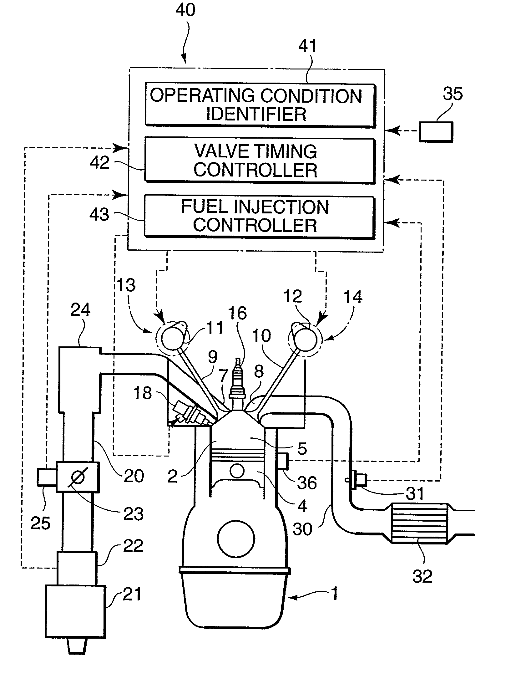
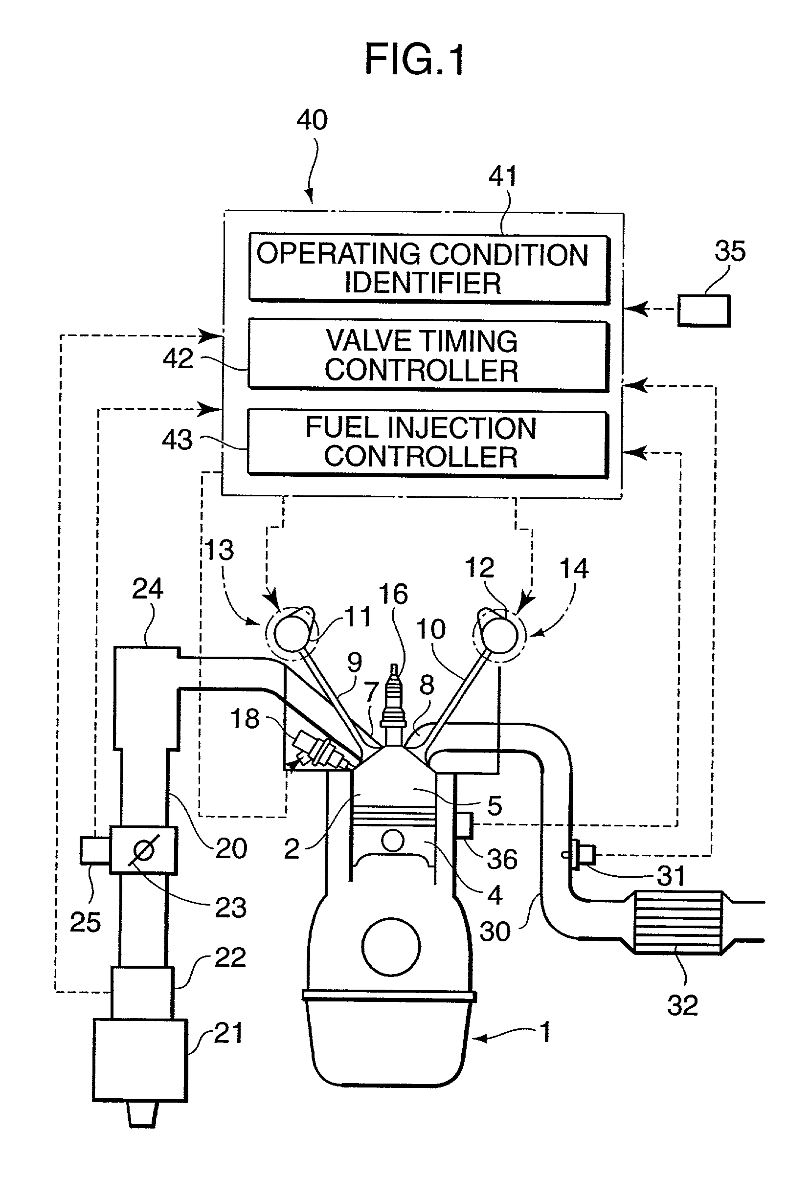
[0037] FIG. 1 is a schematic diagram showing the overall configuration of an automotive four-cycle engine according to a first embodiment of the invention. Designated by the numeral 1 in FIG. 1 is an engine body having a plurality of cylinders 2. There is formed a combustion chamber 5 in each cylinder 2 immediately above a piston 4 which is fitted in a cylinder bore. An intake port 7 and an exhaust port 8 opening into the combustion chamber 5 are opened and closed by an intake valve 9 and an exhaust valve 10, respectively.

[0038] The intake valve 9 and the exhaust valve 10 are caused to open and close by valve operating mechanisms including cam shafts 11, 12, respectively. The valve operating mechanisms for the intake valve 9 and the exhaust valve 10 are provided with respective valve timing adjusters 13, 14 for adjusting valve opening and closing timing. Provided between a cam pull...


PUM


Abstract

A four-cycle engine is provided with valve timing adjusters for adjusting opening and closing timing an and an exhaust valve. In medium- to high-speed ranges in medium- to high-load regions of the engine, a closing point (ExC) of the exhaust valve defined as a point of transfer from an acceleration portion to a constant speed portion on its valve lift characteristics curve is set to a point a specific period before an intake top dead center, and an opening point (InO) of the intake valve defined as a point of transfer from a constant speed portion to an acceleration portion on its valve lift characteristics curve is set to a point after the intake top dead center. In addition, the period from the closing point (ExC) of the exhaust valve to the opening point (InO) of the intake valve is made longer in the medium-speed range than in the high-speed range in the medium- to high-load regions of the engine.

Description

BACKGROUND OF THE INVENTION AND RELATED ART STATEMENT[0001] The present invention relates to a four-cycle engine for a motor vehicle designed to use so-called "internal" exhaust gas recirculation (EGR) in a positive way by causing part of already combusted exhaust gases to remain in a combustion chamber.[0002] EGR is a widely known conventional technique in which an exhaust air line and an intake air line of an engine are connected by an external EGR passage and part of exhaust gases is returned to the intake air line through the external EGR passage to reduce nitrogen oxides (NOx), as described in Japanese Unexamined Patent Publication No. 5-86988, for example. This Patent Publication discloses an external EGR system in which a specific amount of cooled exhaust gas (EGR gas) is re-introduced into a combustion chamber through an external EGR passage which is provided with an EGR cooler and the recirculation rate (EGR rate) is increased in higher-load ranges of the engine, so that NO...

Claims


Application Information

Patent Timeline
Patent Type & Authority Applications(United States)
IPC IPC(8): F01L1/34F02B75/02F02M25/07F02D13/02F02D23/00F02D41/02F02D41/04F02D43/00
CPCF01L1/34F02B2075/027F02D13/0219Y02T10/47F02D41/006F02M25/0752Y02T10/18F02D13/0265F02M26/01Y02T10/12Y02T10/40
Inventor HITOMI, MITSUOMATSUSHITA, YASUSHIOHBA, TADASHIGE
Owner MAZDA MOTOR CORP
Why Eureka
Try Eureka