Microelectronic components and electronic networks comprising DNA
a technology of electronic networks and microelectronic components, applied in the direction of multi-processing unit architecture, semiconductor/solid-state device details, instruments, etc., can solve the problems of microelectronics and logic miniaturization, at current technology, approaching practical and theoretical limits, and the inability to implement nanoscale circuits by existing microelectronics technology,
- Summary
- Abstract
- Description
- Claims
- Application Information
AI Technical Summary
Benefits of technology
Problems solved by technology
Method used
Image
Examples
example 1
Preparation of Linkers
[0166] (a) Disulfide Based Linkers:
[0167] Controlled pore glass (CPG) derivatized with a disulfide group is used for the synthesis (starting from its 3' side) of an oligonucleotide having a free 5' site. The oligonucleotide is prepared using a conventional DNA synthesizer (see scheme in FIG. 13).
[0168] (b) Thiol-based Linkers:
[0169] Linkers are being prepared according to (a) above and the disulfide bond is cleaved to obtain a free thiol.
[0170] (c) Biotin-streptavidin Complex Based Linkers:
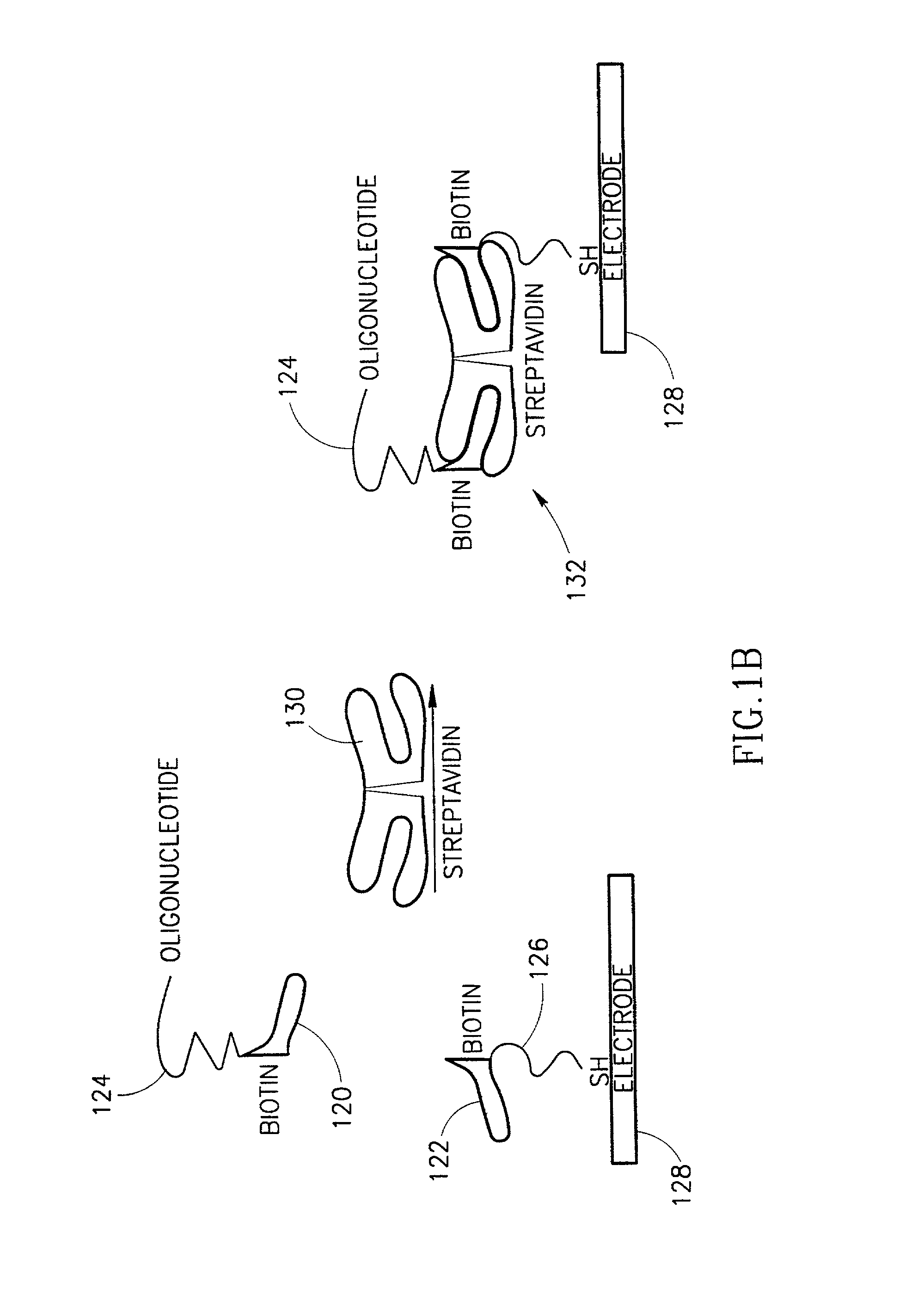
[0171] Biotin moiety is attached to an oligonucleotide having a specific sequence, as known per se. The biotin-oligonucleotide is coupled via a streptavidin molecule to another molecule containing a biotin moiety at one side (see also FIG. 1B) and a thiol or disulfide group on the other side.
[0172] (d) Repressor Based Linkers:
[0173] A nucleic acid binding protein, such as the lac repressor, is covalently attached to a thiol group. A DNA sequence is synthesized having sticky e...
example 2
Attachment of the Linker to an Electrode
[0178] (a) Micropipette Wetting:
[0179] Electrodes are exposed to solutions of the appropriate linkers, for example, by employing pipettes or micropipettes or by any liquid dispensers. Such liquid dispensers may be fixed onto a manipulator that may be computer controlled. Different types of linkers can be deposited on each electrode. Additionally, different types of linkers can be deposited simultaneously or sequentially on different electrodes.
[0180] (b) Jet Printing:
[0181] Ink-jet like printing techniques are used for the selective exposure of different electrodes to different linkers. By utilizing such a technique, it is possible to attain high precision, resolution and to increase rates of production, facilitating large scale production.
[0182] (c) Ab-initio Electrode-linker Synthesis:
[0183] (c1) Using selective masking techniques:
[0184] The well developed technology used for synthesizing DNA sequences may be harnessed for the ab-initio prep...
example 3
Construction of Networks--Production of Junctions
[0192] (a) Production of a Branched Sequence:
[0193] A stable four-arm branched DNA junction is constructed using for example the following sequences:
1 C-G G-C C-G A-T A-T T-A C-G C-G G C A C G A G T T G A T A C C G C G T G C T C A A C T A T G G C C-G C-G G-C A-T A-T T-A G-C C-G
[0194] Careful planning of the sequences allows the fabrication of complex junctions according to a desired design. This branch sequence may be attached to double-stranded fibers using methods known per se.
[0195] (b) Creating a Branch by Enzymatic Reactions:
[0196] The protein recA from E. coli bacteria catalyzes the recombination and construction of a base-paired hybrid to joining two DNA molecules. It can join, in a specific way, a single-stranded DNA with a double-stranded DNA provided that homology exists between the single-stranded and the double-stranded DNA. DNA-binding proteins can extend single-stranded DNA and facilitate DNA annealing by random collisio...
PUM
| Property | Measurement | Unit |
|---|---|---|
| Electrical conductivity | aaaaa | aaaaa |
| Electrical conductor | aaaaa | aaaaa |
| Electric properties | aaaaa | aaaaa |
Abstract
Description
Claims
Application Information
 - R&D
- Intellectual Property
- Life Sciences
- Materials
- Tech Scout
- Unparalleled Data Quality
- Higher Quality Content
- 60% Fewer Hallucinations
Browse by: Latest US Patents, China's latest patents, Technical Efficacy Thesaurus, Application Domain, Technology Topic, Popular Technical Reports.
© 2025 PatSnap. All rights reserved.Legal|Privacy policy|Modern Slavery Act Transparency Statement|Sitemap|About US| Contact US: help@patsnap.com


