
Transparent protective film for polarizing plate, process for producing the same, polarizing plate, and optical film and liquid crystal display using polarizing plate

a technology of transparent protective film and which is applied in the direction of optics, polarising elements, instruments, etc., can solve the problems of reducing the concentration of alkali solution, poor adhesion between the triacetylcellulose film used as the transparent protective film and the polyvinyl alcohol derived film used as the polarizer, and breakdown on the facility with large word load

Inactive Publication Date: 2002-12-12
NITTO DENKO CORP
View PDF5 Cites 32 Cited by
  • Summary
  • Abstract
  • Description
  • Claims
  • Application Information

AI Technical Summary

Benefits of technology

[0008] Another object of the present invention is to provide a process for producing a transparent protective film for polarizing plate without problems attributable to saponification. In particular, in a case the film is subjected to irradiation with UV rays at high power output from a low-pressure mercury lamp etc., the present invention is to provide a process wherein the film having facilitate adhesion surface and no deformation is obtained.
[0021] In the case of irradiation with UV rays at wavelengths of 200 nm or less and 200 to 400 nm to facilitate the film adherent, the irradiation with UV rays is conducted under cooling thereby preventing deformation of the film even upon irradiation with UV rays at high power output and simultaneously rendering the surface thereof hydrophilic in a short time without segregation of a plasticizer thereon, to give a good adherent surface.

Problems solved by technology

The adhesion between the triacetyl cellulose film used as the transparent protective film and the polyvinyl alcohol derived film used as the polarizer is not good.
However, since the alkali solution at high concentration is used, the saponification can be dangerous and easily causes troubles such as breakdown on the facilities with large word load.
Further, when the saponification is conducted for a long time, the concentration of the alkali solution is reduced and the effect of the saponification on improvement of adhesion may be inadequate.
There is a further problem that disposal of the waste alkali solution generates a large amount of wastewater.
However, when such irradiation with UV rays is conducted at low power output, the treatment of facilitating adhesion cannot be effected in a short time, and a long time is required until the treatment of facilitating adhesion is completed.
On the other hand, when the film is subjected to irradiation with UV rays at high power output for reducing the irradiation time, the film may be deformed by heating, or a plasticizer contained in the film is segregated on the surface by heating to prevent the surface being rendered hydrophilic, thus failing to make the surface sufficiently adherent.

Method used


Image

  • Transparent protective film for polarizing plate, process for producing the same, polarizing plate, and optical film and liquid crystal display using polarizing plate
  • Transparent protective film for polarizing plate, process for producing the same, polarizing plate, and optical film and liquid crystal display using polarizing plate

Examples


example 1

[0079] (Preparation of a Polarizer)

[0080] A polyvinyl alcohol film of 80 .mu.m in thickness was dying in 0.3% aqueous iodine, stretched 5 times in 4% aqueous boric acid and 2% aqueous potassium iodide, and then dried at 50.degree. C. for 4 minutes to give a polarizer.

[0081] (Preparation of a Transparent Protective Film)

[0082] One side of a triacetyl cellulose film of 80 .mu.m in thickness (referred to hereinafter as TAC film) was irradiated for 10 minutes with UV rays using a 35 W low-pressure mercury lamp. At the irradiation, the distance between the lamp and the TAC film was 55 mm, and the concentration of ozone was 200 ppm.

[0083] (Preparation of Polarizing Plate)

[0084] The UV-irradiated surface of the transparent protective film was coated with a polyvinyl alcohol type adhesive, and the film was laminated via the adhesive on both sides of the polarizer by a roll laminator, and dried at 60.degree. C. for 4 minutes to form polarizing plate. The thickness of the adhesive layer was 0...

example 2

[0085] The polarizer-adhering surface of a transparent protective film was treated in the same manner as in Example 1 except that in (Preparation of a transparent protective film) Example 1, the film was irradiated for 40 seconds with UV rays from a xenon excimer lamp. Using the resultant transparent protective film, polarizing plate was obtained according to (Preparation of polarizing plate) Example 1.

example 3

[0086] (Preparation of a Transparent Protective Film)

[0087] A TAC film of 80 .mu.m in thickness was placed on a cooling board previously cooled at 10.degree. C., and one side of the film was irradiated for 2 minutes with UV rays from a 350 W low-pressure mercury lamp. At the irradiation, the distance between the lamp and the TAC film was 55 mm, and the concentration of ozone was 100 ppm.

[0088] (Preparation of Polarizing Plate)

[0089] Using the resultant transparent protective film, polarizing plate was obtained according to (Preparation of Polarizing plate) Example 1.


PUM


Abstract

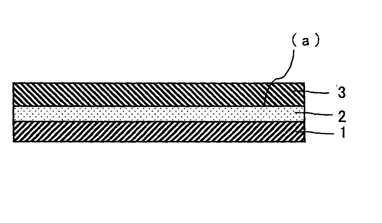
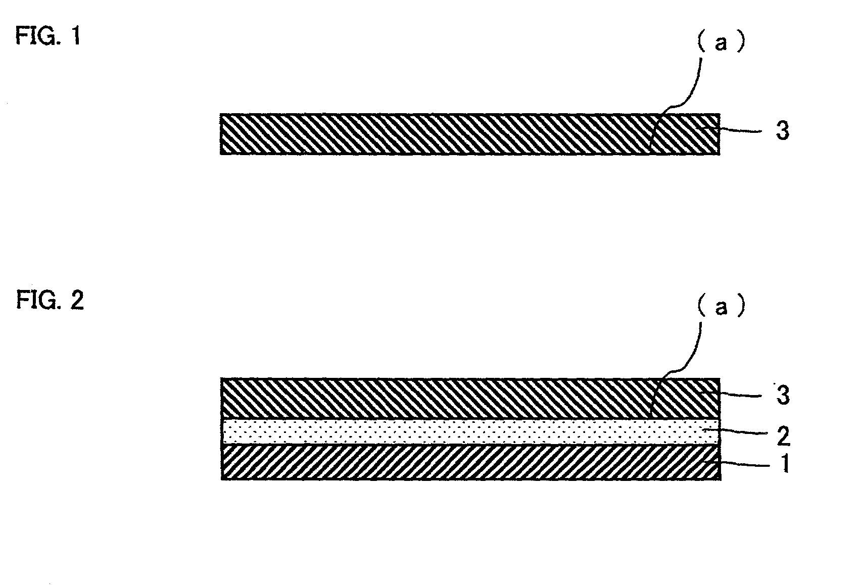
A transparent protective film for polarizing plate being provided via an adhesive layer on at least one surface of a polarizer, wherein a ratio of constituent elements (oxygen ratio / carbon ratio) on the polarizer-adhering surface of the transparent protective film for polarizing plate, which is determined by X-ray photoelectron spectrometry, is larger than 0.75 has facilitate adhesion surface and no deformation without problems attributable to saponification.

Description

[0001] 1. Field of the Invention[0002] The present invention relates to a transparent protective film for polarizing plate and a process for producing the same. Further, the present invention relates to a polarizing plate using the transparent protective film for polarizing plate. The polarizing plate of the invention can be used independently or as an optical film laminating the plate and form a visual display, such as a liquid crystal display, an organic EL display or PDP.[0003] 2. DESCRIPTION OF THE RELATED ART[0004] In a liquid crystal display, it is indispensable that polarizers should be arranged at both sides of a glass substrate that forms a top surface of a liquid crystal panel according to a picture formation method. Generally, polarizing plate laminating a polarizer, comprising a polyvinyl alcohol derived film and a dichroism substance such as iodine, and a transparent protective film such as triacetyl cellulose film is used.[0005] The adhesion between the triacetyl cellu...

Claims


Application Information

Patent Timeline
IPC IPC(8): C08J7/00G02B5/30G02F1/1335
CPCG02B5/3033G02B1/105G02B1/14G02F1/1335
Inventor SAIKI, YUUJITSUCHIMOTO, KAZUKIHARADA, CHIAKIKUSUMOTO, SEIICHIFUJIMURA, YASUO
Owner NITTO DENKO CORP
Learn More