Electrode for rechargeable lithium battery and rechargeable lithium battery

a rechargeable lithium battery and lithium battery technology, applied in the direction of active material electrodes, non-aqueous electrolyte accumulator electrodes, cell components, etc., can solve the problems of large stress in the current collector, internal short circuit, and failure to obtain satisfactory charge-discharge cycle characteristics

Inactive Publication Date: 2003-02-06
SANYO ELECTRIC CO LTD
View PDF1 Cites 33 Cited by
  • Summary
  • Abstract
  • Description
  • Claims
  • Application Information

AI Technical Summary

Benefits of technology

[0011] It is a second object of the present invention to provide an electrode for a rechargeable lithium battery, which incorporates a thin film of active material deposited on a current collector and exhibits improved charge-discharge cycle characteristics, and also provide a rechargeable lithium battery using the same.
[0018] The use of the Cu--Ni--Si or Cu--Cr--Zr alloy for the current collector, in accordance with the second aspect, prevents the occurrence of wrinkling or other type of deformation in the current collector and increases an energy density per volume of the rechargeable lithium battery.
[0020] The deposition of the thin film of active material on the current collector having the above-specified surface roughness Ra results in the provision of irregularities on a surface of the thin film, which correspond to those defined on the current collector surface. The provision of such irregularities on the surface of the thin film of active material increases the possibility that gaps are formed in its regions that extend in a thickness direction from valleys of the irregularities on the current collector surface toward valleys of the irregularities on the surface of the thin film of active material. Expansion and shrinkage of the thin film of active material, generally on or after the first charge-discharge cycle, causes formation of the gaps. The formation of such gaps along the thickness direction is followed by the division of the thin film of active material into columns along these gaps. The division of the thin film of active material into columns results in the provision of spaces that surround the columnar portions. These spaces can accommodate changes in volume of the thin film of active material as it expands and shrinks during charge-discharge cycles. This enables relaxation of a stress produced by expansion and shrinkage of the thin film during the charge-discharge cycles and prevents pulverization and separation of the thin film of active material from the current collector, resulting in obtaining improved charge-discharge cycle characteristics.
[0021] In the first and second aspects of the present invention, it is preferred that a component of the current collector is diffused into the thin film of active material. The diffusion of the current collector component into the thin film of active material improves adhesion between the current collector and the thin film of active material. In the case where the diffused current collector component is an element that does not alloy with lithium, such as copper, alloying of the active material with lithium is suppressed in the diffusion regions. This effectively suppresses expansion and shrinkage of the thin film during a charge-discharge reaction and prevents production of such a large stress that causes separation of the thin film of active material from the current collector.

Problems solved by technology

However, the lithium deposited on charge grows into dendrite, which could cause problematic internal short-circuiting (Solid State Ionics, 113-115, p57(1998)).
However, since these active materials which store lithium via alloying expand and shrink in volume as they store and release lithium, they are pulverized during charge and discharge or caused to separate from the current collector.
This results in the failure to obtain satisfactory charge-discharge cycle characteristics, which has been a problem.
However, in such an electrode for a rechargeable lithium battery, due to the improved adhesion between the current collector and the thin film of active material, a large stress is produced in the current collector as the thin film of active material expands and shrinks during charge and discharge.
This occasionally results in the occurrence of deformation, such as wrinkle formation in the current collector.
As a result, an energy density per volume of the battery is problematically reduced.
The deposition of the thin film of active material on the current collector having the above-specified surface roughness Ra results in the provision of irregularities on a surface of the thin film, which correspond to those defined on the current collector surface.
The provision of such irregularities on the surface of the thin film of active material increases the possibility that gaps are formed in its regions that extend in a thickness direction from valleys of the irregularities on the current collector surface toward valleys of the irregularities on the surface of the thin film of active material.
Expansion and shrinkage of the thin film of active material, generally on or after the first charge-discharge cycle, causes formation of the gaps.
As such, the sequence of burning plating and covering plating results in the formation of large irregularities on a surface of the metal foil 11.
Expansion and shrinkage of the thin film of active material, generally on or after the first charge-discharge cycle, causes formation of the gaps.

Method used


Image

  • Electrode for rechargeable lithium battery and rechargeable lithium battery
  • Electrode for rechargeable lithium battery and rechargeable lithium battery
  • Electrode for rechargeable lithium battery and rechargeable lithium battery

Examples


experiment 1

Examples 1 and 2

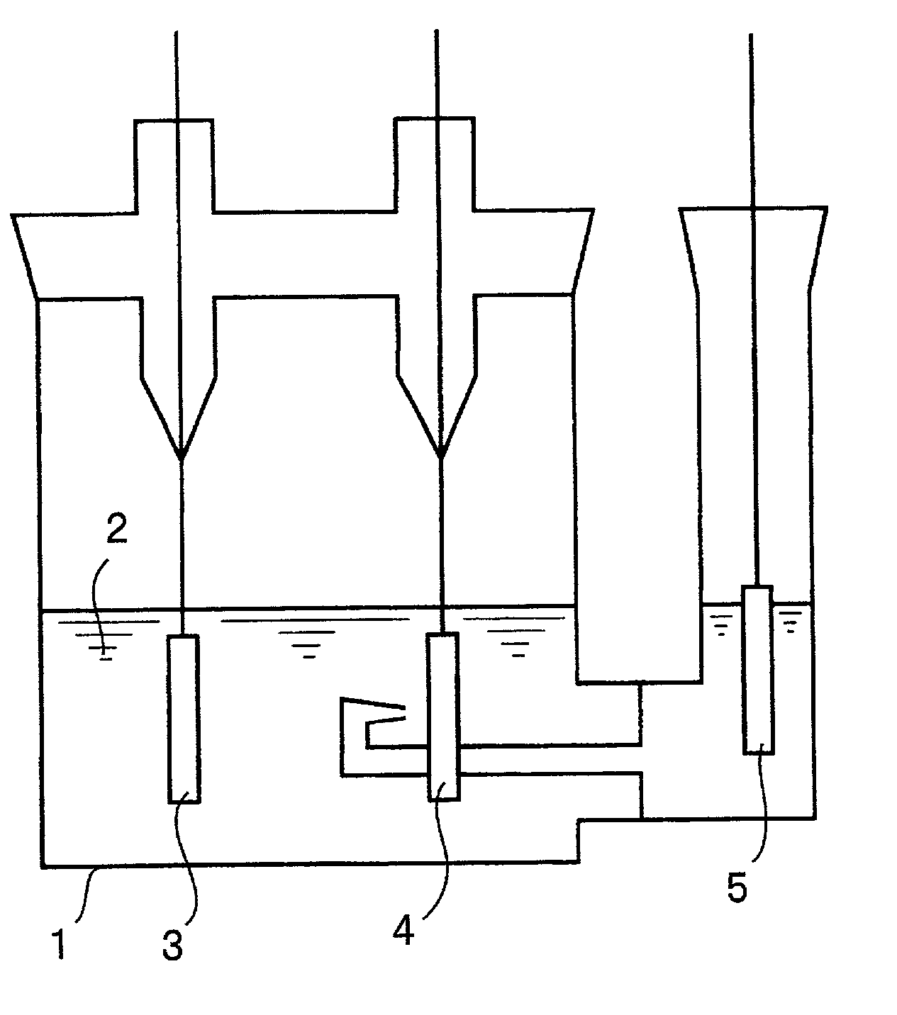
[0055] (Fabrication of Working Electrodes)

[0056] Burning copper plating was carried out electrolytically to form a particulate copper deposit on a Corson alloy foil. Further, copper plating (covering plating) was carried out to form a dense copper deposit on the particulate copper deposit. As a result, a surface-roughened copper alloy foil with enhanced adhesion between the particulate copper deposit and the Corson alloy foil was fabricated. This foil was designated as a current collector a1.

[0057] Next, a Cu--Cr--Zr--Mg alloy foil was subjected to the same treatments as used in the fabrication of the current collector a1, i.e., subjected to the sequence of burning and covering plating treatments to fabricate a current collector a2.

[0058] The thickness, tensile strength, proportional limit, elastic coefficient and surface roughness Ra, measured for each of the current collectors a1 and a2, are listed in Table 1.

[0059] In Table 1, the thickness is given by a value mea...

experiment 2

[0078] (Fabrication of Current Collectors)

[0079] (Current Collector c1)

[0080] A rolled copper foil (thickness of 18 .mu.m) was subjected to a burning plating treatment using a copper sulfate plating solution sold in the market and then to a covering plating treatment to fabricate a current collector c1. The burning plating treatment was performed using a plating solution containing sulfuric acid and copper sulfate at a 20:7 ratio by weight, at a current density of 3 A / dm.sup.2 for a duration of 3 minutes. After this burning plating treatment, the copper foil was washed with water and then subjected to the covering plating treatment. The covering plating treatment was carried out using a plating solution containing sulfuric acid and copper sulfate at a 1:4 ratio by weight, at a current density of 3 A / dm.sup.2 for a duration of 15 seconds.

[0081] (Current Collector c2)

[0082] The procedure used to fabricate the current collector c1 was followed, except that the duration of the burning p...


PUM

PropertyMeasurementUnit
surface roughness Raaaaaaaaaaa
tensile strengthaaaaaaaaaa

Abstract

In an electrode for a rechargeable lithium battery which includes a current collector and a thin film composed of active material that has the capability to store and release lithium either electrochemically or chemically and deposited on the current collector, the current collector comprises a copper alloy and has a tensile strength of 400 N / mm2 or higher, a proportional limit of 160 N / mm2 or higher, an elastic coefficient of 1.1 N / mm2 or higher and a surface roughness Ra of 0.01-1 mum at its surface that carries the thin film of active material thereon.

Description

[0001] 1. Filed of the Invention[0002] The present invention relates to an electrode for a rechargeable lithium battery and a rechargeable lithium battery utilizing the same.[0003] 2. Description of Related Art[0004] Recently, rechargeable lithium batteries have been extensively developed. Such rechargeable lithium batteries exhibit battery characteristics, such as charge-discharge voltage, charge-discharge cycle life characteristics and storage characteristics, which depend largely upon the types of the electrode active materials used.[0005] The use of lithium metal as the negative active material enables construction of batteries which exhibit high energy densities, both per weight and per volume. However, the lithium deposited on charge grows into dendrite, which could cause problematic internal short-circuiting (Solid State Ionics, 113-115, p57(1998)).[0006] On the other hand, rechargeable lithium batteries are reported using an electrode composed of aluminum, silicon, tin or th...

Claims


Application Information

Patent Timeline
Patent Type & Authority Applications(United States)
IPC IPC(8): H01M4/13H01M4/40H01M4/62H01M4/66H01M4/70H01M4/80H01M10/052
CPCH01M4/13H01M4/382H01M4/40H01M4/661H01M10/052Y02E60/122H01M4/386Y02E60/10
Inventor OKAMOTO, TAKASHIFUJIMOTO, HIROYUKIFUJIHARA, TOYOKIIYORI, MASAHIROKAMINO, MARUOMATSUTA, SHIGEKI
Owner SANYO ELECTRIC CO LTD
Why Eureka
Try Eureka