Electrolytic process and apparatus

a technology of electrolysis and process, applied in the field of electrolysis, can solve the problems of short shelf life, unstable chlorine dioxide solution, and inability to be commercially available, and achieve the effect of minimizing the diffusion of chlorite ions

Inactive Publication Date: 2003-05-01
ECOLAB USA INC +1
View PDF53 Cites 29 Cited by
  • Summary
  • Abstract
  • Description
  • Claims
  • Application Information

AI Technical Summary

Benefits of technology

0075] In electrolytic reactors employing a non-permselective membrane to separate the anode compartment from the central compartment, the use of dilute chlorite solutions as described herein and the hygroscopic nature of the non-permselective membrane minimizes diffusion of the chlorite ions from the central compartment to the electrode compartmen

Problems solved by technology

Unfortunately, chlorine dioxide in solution is unstable with an extremely short shelf life and thus, is not commercially available.
One difficulty with electrochemical processes is that it can be difficult to control the generation of undesirable species.
However, known catalytic processes have the disadvantage of becoming greatly deactivated within a matter of days.
Moreover, it has been found that the support materials f

Method used


Image

  • Electrolytic process and apparatus
  • Electrolytic process and apparatus
  • Electrolytic process and apparatus

Examples


example 2

[0077] In this example, a ceramic catalyst material was prepared as follows. A metal oxide precursor solution was prepared by admixing 0.85 grams tetraamineplatinum (II) chloride, 41 ml of 91% isopropyl alcohol, 0.83 ml of 30% ammonium hydroxide and 26 ml of deionized water. The precursor solution was used twice to coat 100 milliliters of SIR-600 resin commercially available from ResinTech, Inc. that had been backwashed and air-dried for about 12 hours. After each coating, the resin was baked at 550.degree. C. for 30 minutes.

example 3

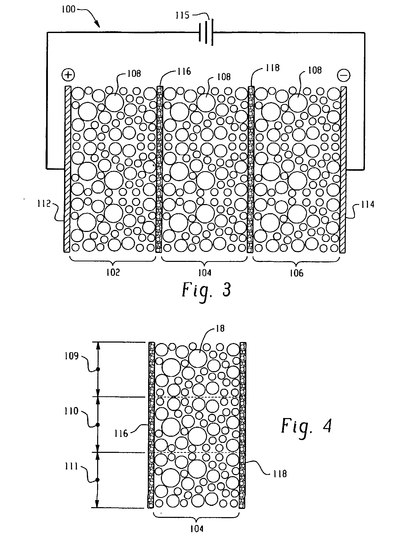
[0078] In this example, electrochemical reactor cassettes were configured as described in FIGS. 4 and 5. The electrode compartments contained SK116 cation exchange resin commercially available from Mitsubishi Chemical. The central compartment contained a particulate material bed of three equal layers. The first layer consisted of SK116 cation exchange resin; the second layer consisted of equal amounts by weight of the SK116 cation exchange resin and the catalyst material; and the third layer consisted of the catalyst material. The catalyst material was prepared in accordance with Examples 1. An overview of the cassette components is shown in Table 1.

1TABLE I Anode DSA, flat sheet Cathode 316L stainless steel, flat sheet Electrode Area 155 cm.sup.2 Membrane Area 155 cm.sup.2 Inter Membrane Spacing 1.27 cm Catalyst Pt impregnated (Example 1) Cation Exchange Resin SK116 (Mitsubishi Chemical) Cation Exchange Membrane CMI-7000 (Membranes International, Inc.)

[0079] Four cassettes containi...

example 4

[0085] In this example, two electrochemical reactor cassettes were configured as described in FIGS. 4 and 5. Each cassette included electrode compartments that contained SK116 cation exchange resin, wherein each compartment was separated from an adjacent compartment by cation exchange membranes (permselective). The central compartment of the first cassette contained a particulate material bed of three equal layers. The first layer consisted of SK116 cation exchange resin; the second layer consisted of equal amounts by weight of the SK116 cation exchange resin and a ceramic catalyst material; and the third layer consisted of the ceramic catalyst material. The ceramic catalyst material was prepared in accordance with Example 1. The central compartment of the second cassette contained a packed bed of Diaion SK1B cation exchange resin. Commercially available from Mitsubishi Chemical, Diaion SK1B is a cross-linked polystyrene cation exchange resin having a cross-linking density of 8%.

[00...


PUM

PropertyMeasurementUnit
Pore sizeaaaaaaaaaa
Pore sizeaaaaaaaaaa
Pore sizeaaaaaaaaaa

Abstract

An electrolytic process and apparatus for oxidizing inorganic or organic species is disclosed. The process and apparatus includes contacting a solution containing the inorganic or organic species with an electrocatalytic material disposed in an electrolytic reactor. Also disclosed are processes for fabricating a catalyst material for use in the electrolytic reactors and processes.

Description

[0001] This application claims priority to U.S. Provisional Application Serial No. 60 / 345,307, filed on Oct. 22, 2001, and U.S. Provisional Application Serial No. 60 / 369,090, filed on Mar. 29, 2002, which are incorporated herein by reference in their entireties.BACKGROUND OF INVENTION[0002] This disclosure relates to electrolysis and more particularly, relates to improved electrolytic processes and apparatuses for the oxidation of inorganic or organic species.[0003] With the decline of gaseous chlorine as a microbiocide, various alternatives have been explored, including bleach, bleach with bromide, bromo-chlorodimethyl hydantoin, ozone, and chlorine dioxide (ClO.sub.2 ). Of these, chlorine dioxide has generated a great deal of interest for control of microbiological growth in a number of different industries, including the dairy industry, the beverage industry, the pulp and paper industries, the fruit and vegetable processing industries, various canning plants, the poultry industry...

Claims


Application Information

Patent Timeline
IPC IPC(8): B01J23/42B01J23/56B01J31/08C25B1/26C25B9/19
CPCB01J23/42B01J23/56C25B9/166C25B1/26C25B9/08B01J31/08C25B9/40C25B9/19
Inventor DIMASCIO, FELICE
Owner ECOLAB USA INC
Why Eureka
Try Eureka