
Multi-layer ceramic fiber insulation tile

a ceramic fiber and insulation tile technology, applied in the field of ceramic fiber tile insulation components, can solve the problems of unsuitable vehicle surface for low density aetb, unsuitable vehicle surface for cosmonautic vehicles, and high thermal conductivity, and achieve the effects of improving thermal barrier tiles, high temperature durability, and high strength

Inactive Publication Date: 2003-05-01
THE BOEING CO
View PDF0 Cites 31 Cited by
  • Summary
  • Abstract
  • Description
  • Claims
  • Application Information

AI Technical Summary

Benefits of technology

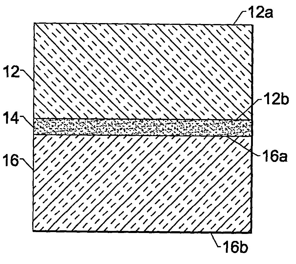
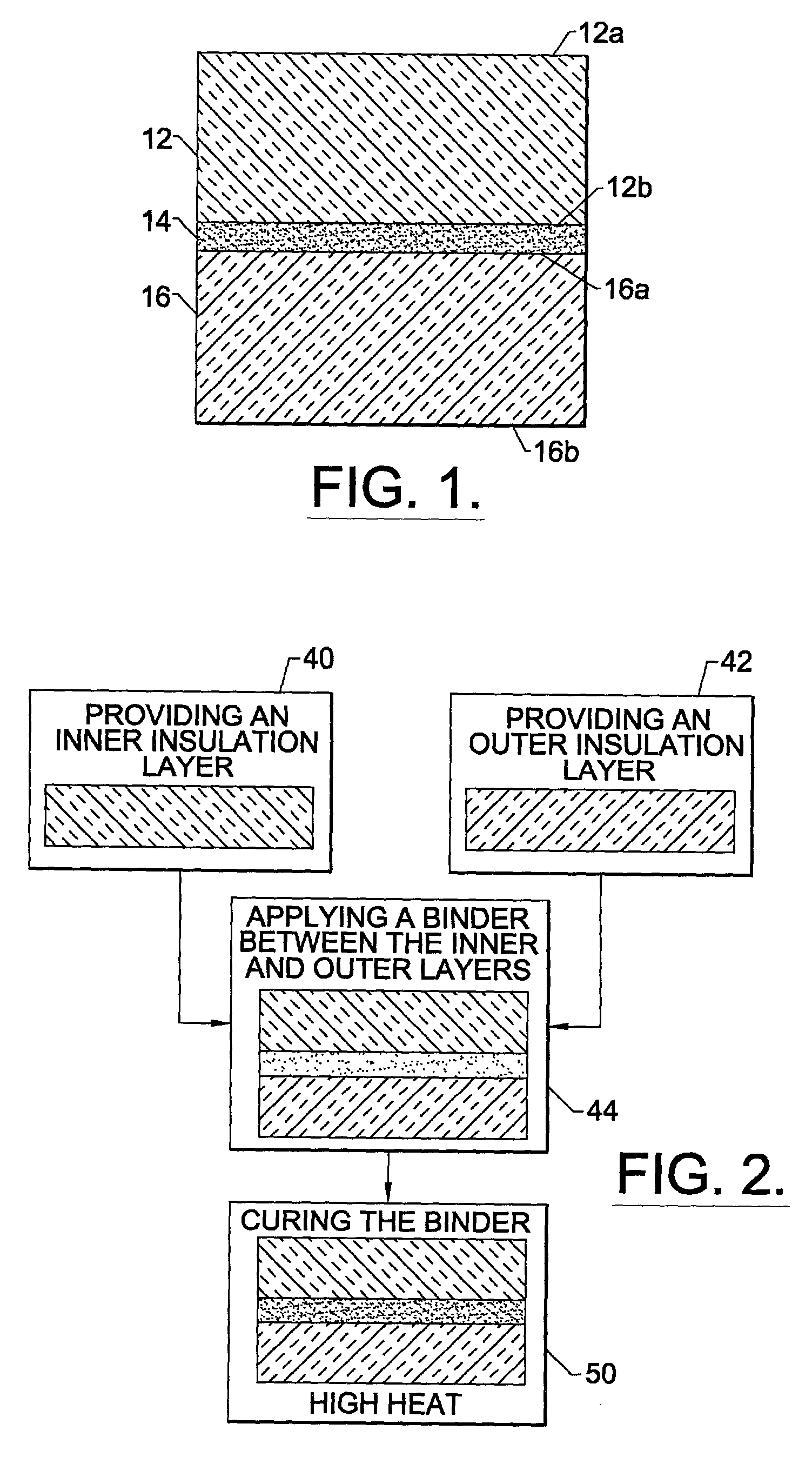
[0008] A multi-layer alumina enhanced thermal barrier tile and method of making the tile are therefore provided that exhibit the high strength and high temperature durability of high density AETB tile while exhibiting the superior insulative properties of low density AETB. The invented multi-layer tile achieves the advantages of both high density and low density AETB by bonding a layer of the low density AETB to a layer of the high density AETB to form a unitary multi-layer tile material. When used on a reusable launch vehicle with the high density AETB layer facing the outer mold line, the high density AETB layer of the tile resists slumping in the high temperature environment while the low density AETB layer, facing the inner mold line, provides superior insulative properties without the need to endure extremely high temperatures that are absorbed by the high density layer. Use of a low density layer also advantageously reduces the overall weight of the tile.
[0009] The multi-layer tile material is produced from different density AETB materials which are produced by conventional methods. The insulation layers are bound together by a high strength, high temperature alumina or silica binder having a coefficient of thermal expansion similar to that of the insulation layers. Use of the multi-layered AETB tile allows the problems of tile slumping and of insufficient heat management to be overcome.

Problems solved by technology

However, low density AETB cannot be used on vehicle surfaces which experience the hottest temperatures, those near 2900.degree. F., due to the tendency of the low density tile to slump, or shrink, which requires replacement of the tile after use.
High temperature applications call for the use of high density AETB, such as 16 lbs / ft.sup.3 or 20 lbs / ft.sup.3, which is able to resist slumping but results in higher thermal conductivity and adds undesired weight to the vehicle.

Method used


Image

  • Multi-layer ceramic fiber insulation tile
  • Multi-layer ceramic fiber insulation tile
  • Multi-layer ceramic fiber insulation tile

Examples


example 1

[0035] Two small samples of AETB insulation tile having different densities were prepared, and a flat surface was machined on each sample.

[0036] A binding mixture was prepared using RCG glass composition composed of 95 wt % RCG glass and 7 wt % Methocellulose organic binding material. A denatured alcohol solvent was used to adjust viscosity.

[0037] A coating of the binding mixture was sprayed on the flat surfaces of each tile and the coated tiles were allowed to sit at room temperature for a period of 30 minutes. The two respective tiles were mated together. A small weighted object was placed upon the top surface of the top insulation layer in order to hold the top layer in intimate contact with the bottom layer.

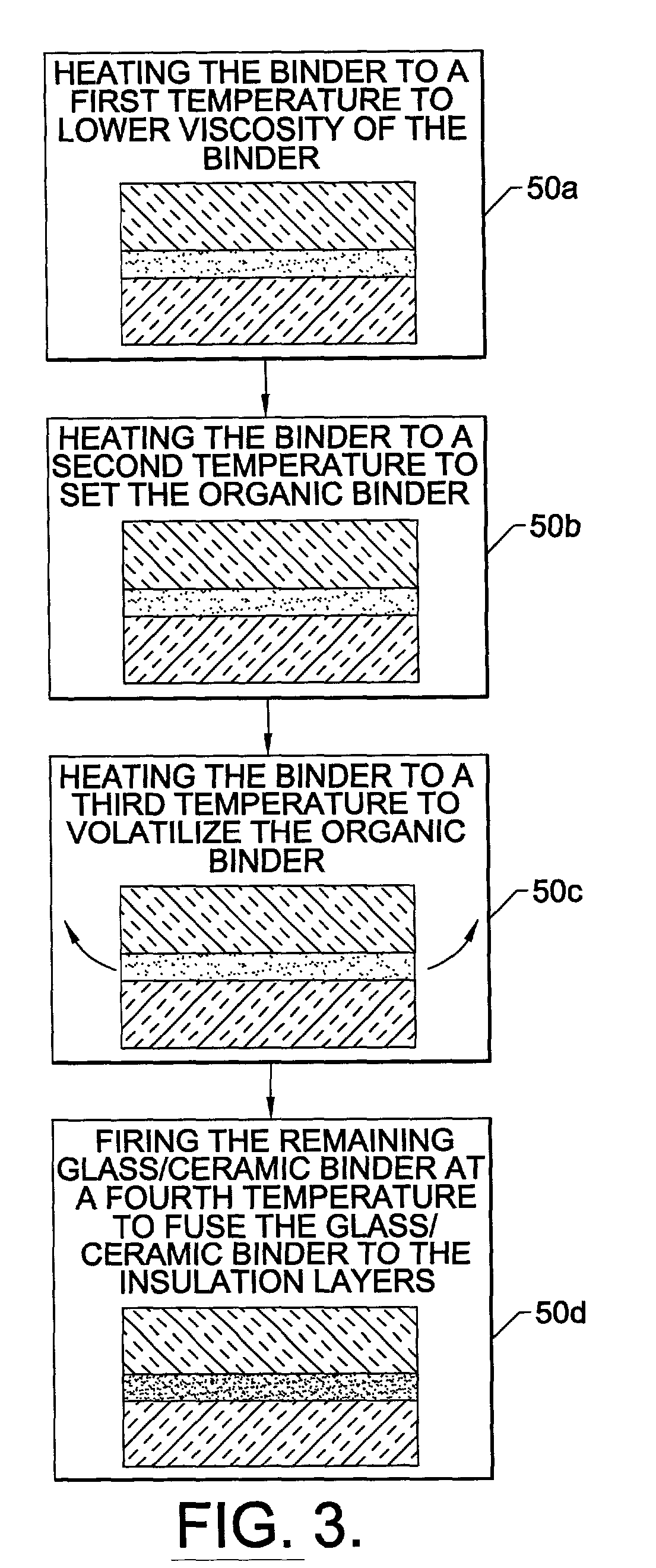
[0038] The tile assembly was slowly heated to about 350.degree. F. for a period of 30 minutes. The assembly was then moved to a furnace, where it was heated slowly to about 1000.degree. F. At approximately 800.degree. F., the heating rate was slowed such that the temperature ...

example 2

[0039] Two small samples of AETB insulation tile having different densities were prepared, and a flat surface was machined on each sample.

[0040] A binding mixture was prepared using 95 wt % Ferro Electronic Glass EG0002, ceramic bonding material, and 5 wt % ethocellulose organic binding material. A butyl carbitol acetate solvent was used to adjust the viscosity of the bonding mixture to a medium paste.

[0041] A coating of the binding mixture was applied to the flat surfaces of each tile and the coated tiles were allowed to sit at room temperature for a period of 30 minutes. A second coating of the binding mixture was applied to the flat surfaces, and the flat surfaces of the two respective tiles were mated together. A small weighted object was placed upon the top surface of the top insulation layer in order to hold the top layer in intimate contact with the bottom layer.

[0042] The tile assembly was slowly heated to about 350.degree. F. for a period of 30 minutes. The assembly was the...

example 3

[0043] Two small samples of AETB insulation tile having different densities were prepared, and a flat surface was machined on each sample.

[0044] A binding mixture was prepared using 90 wt % Ferro Electronic Glass EG0002 ceramic bonding material, and 10 wt % epoxy organic binding material. Acetone was used as a solvent to adjust the viscosity of the bonding mixture to a medium paste.

[0045] A coating of the binding mixture was applied to the flat surfaces, and the flat surfaces of the two respective tiles were mated together. The assembly was placed in a vacuum bag apparatus and a light vacuum was applied in order to hold the top layer in intimate contact with the bottom layer.

[0046] The tile assembly was slowly heated to about 350.degree. F. for a period of 30 minutes. The assembly was removed from the vacuum bag and moved to a furnace, where it was heated slowly to about 1000.degree. F. At approximately 800.degree. F., the heating rate was slowed such that the temperature was increa...


PUM


Abstract

A multi-layer tile material produced from layers of alumina enhanced thermal barrier material having different densities. The insulation layers are bound together by a high strength, high temperature alumina or silica binder having a coefficient of thermal expansion similar to that of the insulation layers. Use of the multi-layered tile allows the problems of tile slumping and of insufficient heat management associated with low density alumina enhanced thermal barrier tile to be overcome.

Description

FIELD OF THE INVENTION[0001] The present invention relates to ceramic fiber tile insulation components for the protection of a reusable launch vehicle such as the space shuttle.BACKGROUND OF THE INVENTION[0002] Reusable launch vehicles (RLVs), such as the space shuttle, repeatedly travel into or beyond the Earth's upper atmosphere and then return to the Earth's surface. During flight, the RLVs experience extreme temperatures, ranging from -250.degree. F. while in orbit to nearly 2900.degree. F. upon reentry to the atmosphere. Because of the extreme temperatures, the vehicle and its contents must be protected by a thermal protection system.[0003] Thermal protection systems for RLVs are constructed from a large number, usually several thousand, of insulative tiles. The tiles function to insulate the vehicle from the environment and to radiate and reflect heat away from the vehicle. In addition to protecting the vehicle from environmental heat sources, the insulative tiles also provide...

Claims


Application Information

Patent Timeline
IPC IPC(8): B32B19/04B32B19/06C04B37/00
CPCB32B19/04B32B19/06B32B2305/20C04B37/005C04B2235/483C04B2235/5224C04B2235/5228C04B2235/5232C04B2235/608C04B2235/94C04B2235/9607C04B2237/062C04B2237/064C04B2237/10Y10S428/92Y10T428/249928Y10T428/24992Y10T156/10
Inventor DICHIARA, ROBERT A. JR.MYERS, FRANKLIN K.
Owner THE BOEING CO
Learn More