
Mechanical composting

a mechanical and composting technology, applied in the field of mechanical composting, can solve the problems of difficult to handle biomass and other materials in bulk, affecting the productivity of the column, and increasing the height of the column for productive output, and requiring a method on difficult combinations of biomass inputs

Inactive Publication Date: 2003-05-01
WILLSON BROWN ASSOC
View PDF0 Cites 9 Cited by
  • Summary
  • Abstract
  • Description
  • Claims
  • Application Information

AI Technical Summary

Benefits of technology

[0017] Operation of the composting system is continuous and operates on a plug flow principle using controlled shrinkage of biomass materials during their descent through the vertical chamber such that the effects of pressure on the walls of the chamber means that straight sided walls can be used instead of negatively inclined walls as is commonally known in the art and this simplifies construction methods and reduces costs.
[0032] The major advantage of the VCU is the ability to site the system closer to urban areas reducing collection and disposal costs and enhancing sales of finished products. It also enables the use of corporate, commercial and institutional units on-site.

Problems solved by technology

At present biomass and, in particular food waste, wood waste, wood chips, sewage sludge and even some hazardous wastes and other materials are difficult to handle particularly in bulk.
A number of composting systems are currently available for handling this type of material, however most of these are costly and produce odour, which means that the machines must be located in the countryside, away from urban areas.
This is opposed to the more recent need to reduce landfill volumes because of their cost of establishment and operation and remediation of sewage ponds after their useful life has ended or urban encroachment has made them unpopular.
High induced air rates commonly used render the bottom levels of a vertical thermic pile ineffective thus adding to the height of the column for productive outputs.
This method may be required on difficult combinations of biomass inputs or in cases of soil remediation.
It is this action which makes odour clean up issues much larger and harder to control.
The introduction of large amounts of excess air renders a vertical in-vessel composting system inefficient in its lower column section while requiring large amounts of energy.

Method used


Image

  • Mechanical composting
  • Mechanical composting
  • Mechanical composting

Examples


Embodiment Construction

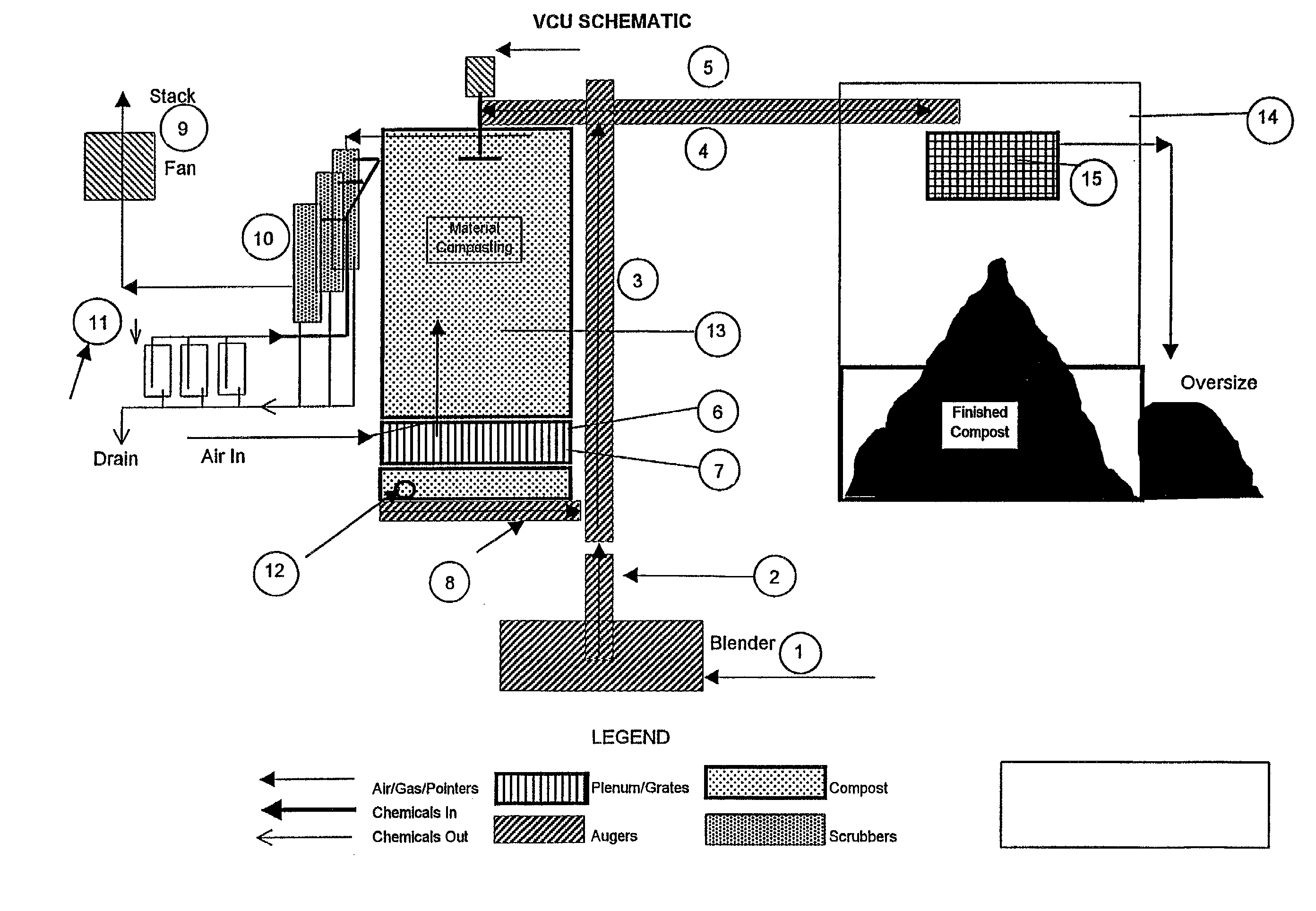
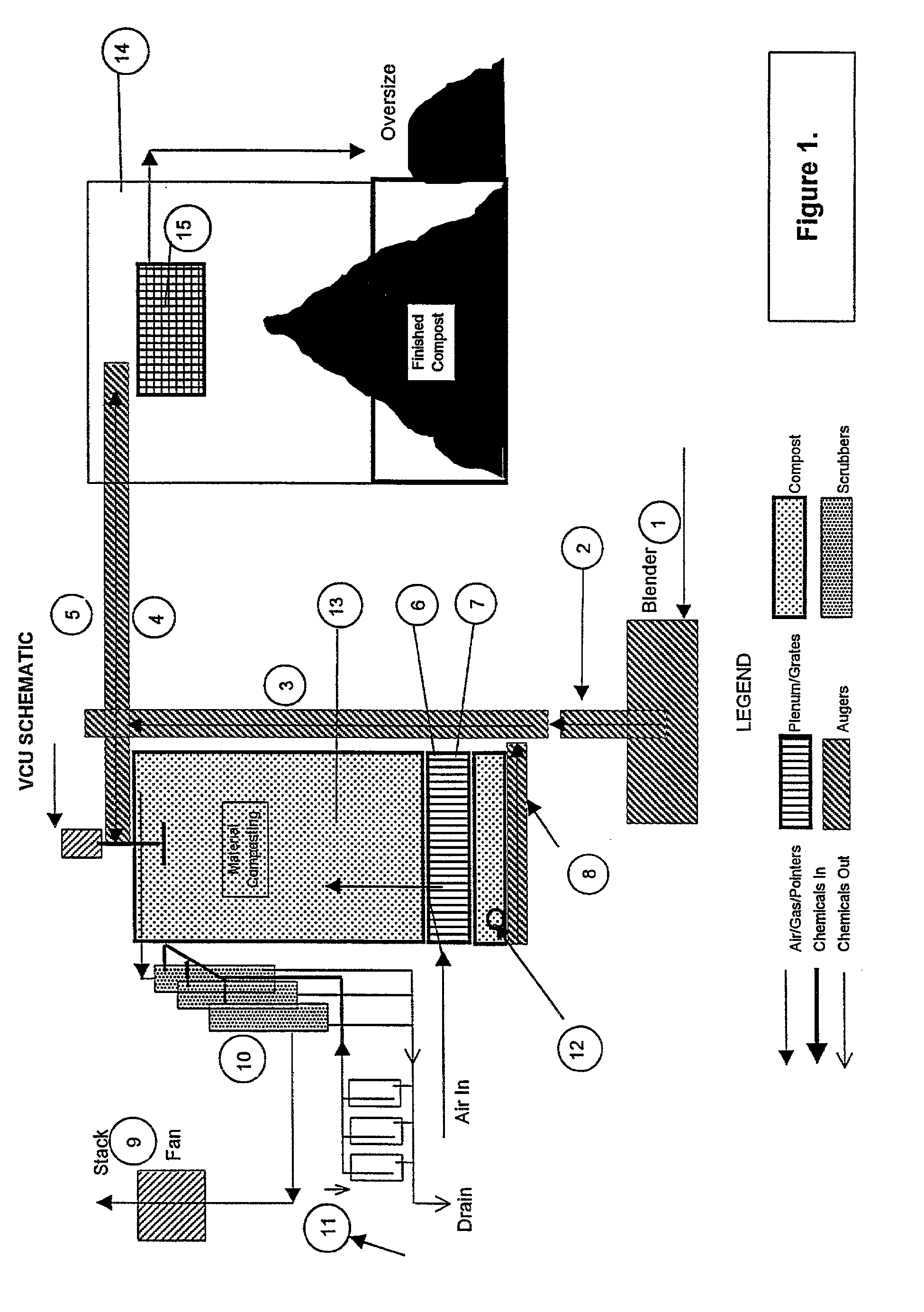
[0041] The specifications for such a unit (FIG. 1) are set out below:

1 Typical Commercial Specifications: (Smaller Domestic and Institutional units not listed) Sizes: Daily production rates (m3) of: 0.2, 1.0, 5.0, 25, 50, 100 Accelerated production rates (m3) of: 0.5, 2.0, 10, 50, 200 Chamber 5, 20, 50, 250, 500, 1000 Sizes: Air Use: Typically 1.25 scm / min (42 scfm) Power Air: 10 watts / m3 Usage: Feeding / Shredder: 950 watts / m3 Controls: 5 watts / m3 Feed Materials to be processed are placed into a blender (1) to System: be mixed together with any additives. Blended material is then sent by the stuffing auger (2) to vertical (3) and transverse (4) augers. Input is distributed evenly by rotating disk (5). Automatic level control allows enough space to empty the feed system. The feed hopper is closed off after filling to maintain negative pressure throughout the system and avoid residual odours. A small batch of fresh green waste can be run through the system to scarify and clean out the ...


PUM


Abstract

A composting system and method incorporating a vertical insulated composting tower with one or more compartments. The base of each compartment being fitted with a plenum and grate through which air is self induced and output is regularly removed. The method of composting biodegradable waste material utilises a plug flow principle including inducing low air flow rates through a compost pile using column energy. The method utlises high temperature pyro / thermopylic micro-organism activity in the compost pile and retaining pile energy above levels by controlling the induced air flow. Evolved gas extraction is utilised in the compost pile and constant biofilm is maintained by combined cycle anaerobic / aerobic operation.

Description

[0001] The invention relates to improved composting and particularly to an improved mechanical composting machine or system.BACKGROUND TO THE INVENTION[0002] At present biomass and, in particular food waste, wood waste, wood chips, sewage sludge and even some hazardous wastes and other materials are difficult to handle particularly in bulk.[0003] A number of composting systems are currently available for handling this type of material, however most of these are costly and produce odour, which means that the machines must be located in the countryside, away from urban areas.[0004] Composting of biomass has been practised for thousands of years in various forms. Some composting is natural, as occurs in the humification of material decaying by biological action in natural environments. Mankind has made many attempts to enhance and speed up this process using manually assembled heaps of organic matter and, more recently, mechanical devices. This has arisen from the centralisation of pop...

Claims


Application Information

Patent Timeline
IPC IPC(8): C05F9/02B09B3/00C05F17/02
CPCC05F17/0247C05F17/0294C05F17/027Y02P20/145C05F17/95C05F17/957C05F17/979Y02W30/40
Inventor BROWN, PAULWILLSON, GRAHAM FAIRLIE
Owner WILLSON BROWN ASSOC
Learn More