Hybrid optical amplifier coupling raman fiber amplifier semiconductor optical amplifier

Active Publication Date: 2003-05-15
THE IND & ACADEMIC COOPERATION & CHUNGNAM NAT UNIV
View PDF9 Cites 20 Cited by
  • Summary
  • Abstract
  • Description
  • Claims
  • Application Information

AI Technical Summary

Problems solved by technology

However, SOA has also disadvantages that the power output is low, the noise figure is worse than typical EDFAs, and the cross-talk between channels is serious.
Researches to use SOA's in a metro-WDM system which is in great demand are restrictively performed.
However, it is not widely accepted because it has difficulties to use due to a relatively high noise figure and an low output power in order to avoid significant cross-talks between channels.
However, when RFA is not used together with other amplifiers such as an EDFA, but is used alone, its use is actually very difficult because a pump light of about 1W should be inseterted into a single mode optical fiber in order to get a sufficient gain, i.e., more than 2

Method used


Image

  • Hybrid optical amplifier coupling raman fiber amplifier semiconductor optical amplifier
  • Hybrid optical amplifier coupling raman fiber amplifier semiconductor optical amplifier
  • Hybrid optical amplifier coupling raman fiber amplifier semiconductor optical amplifier

Examples


first embodiment

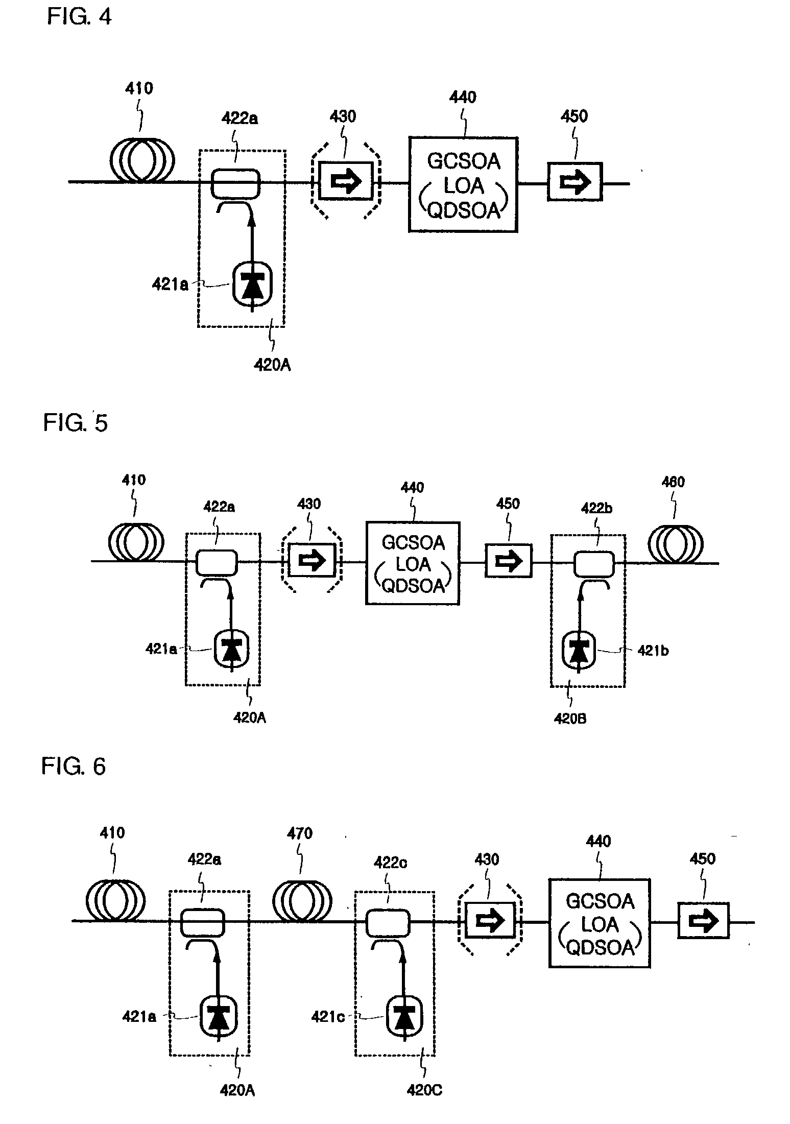
[0033] FIG. 4 is a block diagram illustrating a hybrid optical amplifier that couples a Raman fiber amplifier and a gain clamped semiconductor optical amplifier according to the present invention.

[0034] As shown in FIG. 4, the hybrid optical amplifier includes a transmission optical fiber 410, an Raman amplification laser diode 421a, a wavelength division multiplexer 422a which passes an incident signal light and irradiates a laser light from the Raman amplification laser diode 421a in a reverse direction of the incident signal light, an isolator 430 which isolates a Raman optical amplifying portion 420A from a gain clamped semiconductor optical amplifier 440, and the gain clamped semiconductor optical amplifier 440 which amplifies a optical signal passing through the isolator 430. Therefore, an optical signal incident to the transmission optical fiber 410 is irradiated to the isolator 430 through the wavelength division multiplexer 422a.

[0035] At this time, a laser light generated ...

second embodiment

[0037] FIG. 5 is a block diagram illustrating a hybrid optical amplifier coupling a Raman fiber amplifier and a gain clamped semiconductor optical amplifier according to the present invention. The hybrid optical amplifier of FIG. 5 includes a Raman optical amplifying portion 420B and a transmission optical fiber 460 additionally arranged to a rear portion of the hybrid optical amplifier of FIG. 4, and has a configuration in which the optical signal is amplified through the gain clamped semiconductor optical amplifier 440 and becomes incident through the second isolator 450 and is Raman-amplified once more.

[0038] Therefore, whereas the output of the gain clamped semiconductor optical amplifier is restricted (a currently available product outputs about 10 dBm) and so a transmission is difficult when either a long distance transmission or a high output is required, the hybrid optical amplifier of FIG. 5 can perform an additional amplification of more than 5 dB using the relatively low ...

third embodiment

[0039] FIG. 6 is a block diagram illustrating a hybrid optical amplifier coupling a Raman fiber amplifier and a gain clamped semiconductor optical amplifier according to the present invention. The hybrid optical amplifier of FIG. 6 is a structure that inserts a dispersion compensating fiber (DCF) 470 to compensate a chromatic dispersion of a digital signal accumulated while the optical signal passes through the transmission optical fiber. Additional loss comes from the DCF, components for add / drop of channels, or a variable attenuator. At this time, the loss is compensated by Raman-amplifying the DCF 470 in a forward or reverse direction. Additional gain can be obtained by supplying a higher pump power if needed. In this case, a signal amplification following the DCF 470 is the same as performed in the hybrid optical amplifier of FIG. 4.


PUM


Abstract

The present invention discloses a hybrid optical amplifier coupling a Raman fiber amplifier and a semiconductor optical amplifier, comprising: a laser diode generating and irradiating a laser light for a Raman optical amplification; a wavelength division multiplexer passing an incident signal light and irradiating a laser light irradiated from the laser diode in a reverse direction of the incident signal light; and a gain clamped semiconductor optical amplifier amplifying an optical signal irradiated from the wavelength division multiplexer.

Description

[0001] 1. Field of the Invention[0002] The present invention relates to an optical amplifier for optical communications, and more particularly, to a hybrid optical amplifier that couples a Raman fiber amplifier and a semiconductor optical amplifier to perfectly operate in WDM optical transmission systems. The hybrid optical amplifier uses both a gain clamped semiconductor optical amplifier and a Raman fiber amplifier, so that a sufficiently high gain and a sufficiently low noise figure are secured. In addition, the hybrid optical amplifier works perfect in WDM optical networks, in which the number of channels are dynamically changed by an add / drop of channels or the like. The semiconductor optical amplifier and Raman fiber amplifier are packaged in a small size without using an optical fiber, so that the hybrid optical amplifier is convenient to use and low in cost.[0003] 2. Description of Related Art[0004] To cope with a recently rapidly increasing optical communication capacity, d...

Claims


Application Information

Patent Timeline
IPC IPC(8): H01S3/067G02B6/00H01S3/10H01S3/30H01S5/50
CPCH01S3/06725H01S3/06754H01S5/5072H01S3/302H01S5/50H01S3/10023G02B6/00
Inventor LEE, DONGHAN
Owner THE IND & ACADEMIC COOPERATION & CHUNGNAM NAT UNIV
Why Eureka
Try Eureka