Eureka AIR delivers breakthrough ideas for toughest innovation challenges, trusted by R&D personnel around the world.

Induction heating system

Inactive Publication Date: 2003-06-19
AJAX MAGNETHERMIC CORP
View PDF0 Cites 11 Cited by
  • Summary
  • Abstract
  • Description
  • Claims
  • Application Information

AI Technical Summary

Benefits of technology

[0005] The present invention utilizes a compact inverter having a clean DC input and components which fit into a relatively small housing with a volume of less than about 100 cubic inches. By developing a special induction heating system for use in a confined space, the advantages of induction heating can be employed for various heating functions, in such confined space as under the hood of a motor vehicle. Consequently, the required heating operations in such a confined space can enjoy the advantages of induction heating with its efficiency, environmental friendly nature, and ease of control.
[0007] In accordance with still a further aspect of the present invention the clean DC voltage is preferably in the range of 12 to 24 volts DC which is substantially less than 20 volts and the general upper limit of 50 volts DC. The power supply has a lower input limit of 6 volts DC. In one aspect of the invention, the inductor of the inverter is an induction heating coil. In an other aspect, the inductor is a primary winding of an output transformer having a secondary winding forming the induction heating coil. Although the frequency of the heating system can be as low as 1.0 kHz, it is preferably in the range of 10-20 kHz to drastically reduce this size of those components constituting the inverter. By such high frequency control of the gating circuit, the housing for the inverter can be reduced to substantially less than 100 cubic inches so that it easily fits under the hood of a motor vehicle or the cowling an internal combustion driven implement. The heating system is preferably driven by a switching circuit operated between 10 kHz and 20 kHz. By this high frequency operation, the compactness of the inverter is possible. The advantage of an induction heating system of the type to which the present invention is directed is the ability to operate at a high frequency to produce a relatively low reference depth of heating by the output induction heating coil for efficient heating of related constituents within a very confined compartment.
[0009] In accordance with another aspect of the present invention, there is a dead time between the pulses to allow the natural frequency of the two combined conductive paths to prepare for reversing of the switches. This is another advantage of using high frequency. The dead time can be reduced between the pulses that control the driven frequency determining the actual heating output of the novel induction heating system.
[0012] Still a further object of the present invention is the provision of a compact induction heating system, as defined above, which system utilizes a unique high frequency operated inverter for converting clean DC current to the high frequency heating current. A clean DC current is a current that is not generated by a rectifier and thus has a minimal ripple factor that will adversely effect the operation of the high frequency inverter. Such clean DC is available in an implement or vehicle driven by an internal combustion engine wherein the DC current is generated by an alternator and stored in a battery for use in the emission system of the internal combustion engine.

Problems solved by technology

Consequently, such power supplies cannot be fit into a small compartment, such as the area under the hood of a motor vehicle.
Further, a heating system to be used in association with an internal combustion engine cannot involve induction heating since there is no source of alternating current to drive the power supply for the induction heating coil.

Method used


Image

  • Induction heating system
  • Induction heating system
  • Induction heating system

Examples


Embodiment Construction

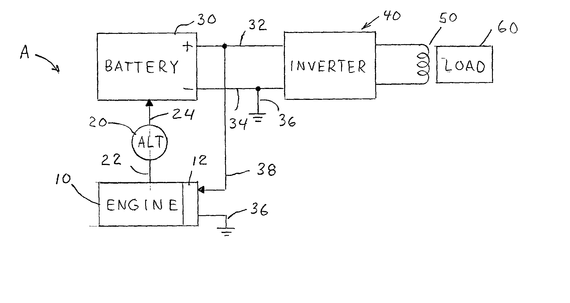
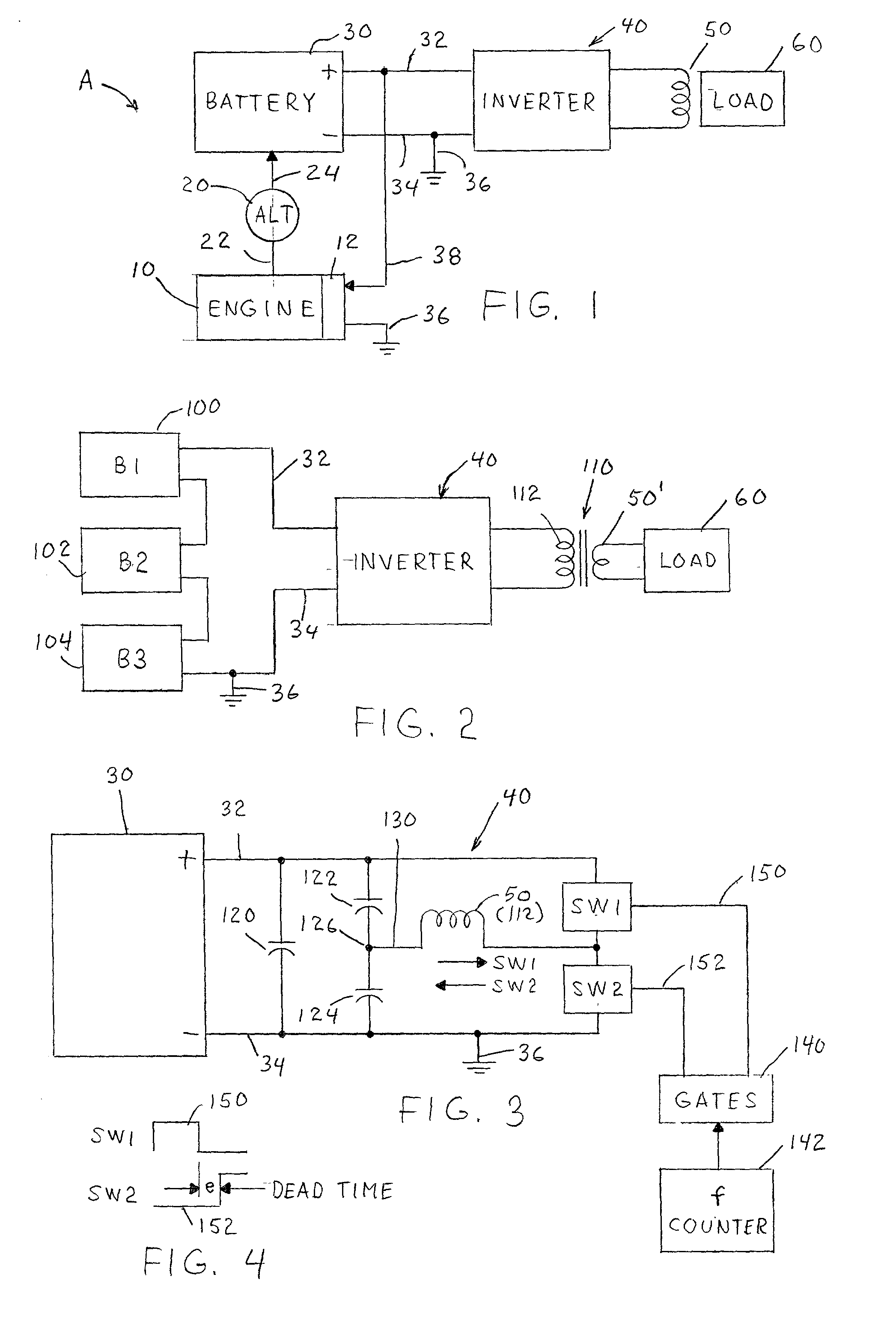
[0020] Referring now to the drawings wherein the showings are for the purpose of illustrating preferred embodiments of the present invention and not for the purpose of limiting the same, FIG. 1 shows an induction heating system as constructed in accordance with the present invention and used with an internal combustion engine 10 having a standard condition system 12 whereby alternator 20 is driven by shafts 22 during operation of engine 10. In practice, the output voltage in line 24 is 12 volts DC for storing electrical energy in battery 30 to produce a clean DC current between leads 32, 34. In accordance with standard practice, the negative lead 34 is grounded at terminal 36. By this architecture, the ignition system is powered by a clean DC current directed to ignition system 12 by lead 38 connected to positive lead 32. A novel high frequency inverter 40, the details of which will be explained later, produces high frequency currents to an induction heating coil 50 for inducing a v...


PUM


Abstract

A compact induction heating system for use on an internal combustion engine driven implement having an engine driven alternator to generate DC current for storage in a battery used as a source of clean DC current of less than 50 volts for ignition of fuel in the engine, the system comprises a high frequency inverter with an input connected to the clean DC current source, a first current conductive path including a first capacitor and a first switch closed to cause DC current to flow in the first path and across the first capacitor, a second current conductive path including a second capacitor and a second switch closed to cause DC current to flow in the second path and across the second capacitor, a single load inductor in both of the paths with DC current flowing in a first direction through the inductor when the first switch is closed and in a second opposite direction through the inductor when the current is closed and a gating circuit to alternately close the switches at a driven frequency to control heating by the load inductor.

Description

[0001] The present invention relates to the art of induction heating and more particularly to a unique compact induction heating system for use under the hood or cowling of internal combustion engine drive implement.[0002] Induction heating involves the use of an induction heating coil that is driven by alternating currents to induce voltage and thus current flow in a work piece encircled by or associated with the induction heating coil. Such technology has distinct advantages over convection heating, radiant heating and conduction heating in that it does not require physical contact with the heated work piece or circulating gasses to convey combustion type heat energy to the work piece. Consequently, induction heating is clean, highly efficient and usable in diverse environments. However, induction heating by work piece associated conductors normally involve power supplies connected to an AC line current. Such heating power supplies are constrained by the frequency of the incoming ...

Claims


Application Information

Patent Timeline
IPC IPC(8): H05B6/04H05B6/06
CPCH05B6/06H05B6/04
Inventor MORRISON, WILLIAM ADAM
Owner AJAX MAGNETHERMIC CORP
Why Eureka
Eureka Blog
Learn More