Modular equipment apparatus and method for handling labware

a technology of modular equipment and labware, applied in the direction of instruments, computing, electric digital data processing, etc., can solve the problems of insufficient development of robots capable of performing relatively complex tasks, significant differences between the application of industrial robots, and plainly too long time period

Inactive Publication Date: 2003-12-04
HUDSON CONTROL GROUP
View PDF7 Cites 43 Cited by
  • Summary
  • Abstract
  • Description
  • Claims
  • Application Information

AI Technical Summary

Benefits of technology

[0025] These components are used to configure the desired workcell. The robotic arms provide rapid movement of the labware from the conveyor to the nest of a microplate-based device such as a reader or washer. Alternative embodiments will allow direct incorporation of third party designs into the system, producing even simpler and faster configurations. For example, a plate washer's nest could be directly integrated with a conveyor, allowing plates to rapidly be moved into and out of position for washing. Other embodiments can be configured around liquid handlers as well. The labware can be moved directly across a liquid handler deck, and additional devices from any vendor can added to the system to create a more powerful workstation. For example, a liquid handler that is expanded with a stacker, a reader and a washer.
[0026] The system can be programmed to communicate by serial commands, dynamic data exchange (DDE), ActiveX, small computer system interface (SCSI), or relay control, and possesses the ability to develop functioning interfaces within reasonable timeframes and costs. More than 80 lab automation integrations that have been developed by Hudson will be available for SoftLinx. These include laboratory automation devices that have been integrated by Hudson Control Group and / or third parties. The laboratory automation devices include advanced liquid handling systems (e.g. Beckman Coulter Biomek.RTM.2000); pipetting stations and basic liquid handling systems (e.g. Beckman Coulter Multimek.TM. / Multipette), dispensers (e.g. Bio-Tek.RTM. Microfill AF 1000; Washers (e.g. Bio-Tek.RTM. E403 / 404); sealers (e.g. Abgene.TM. ALPS 300 Plate Sealer); incubators / freezers / storage devices (e.g. Jouan Robotics MolBank.TM.; mass spectrometers (e.g. Micromass.TM. MUX); thermal cyclers (e.g. MJ Research.TM. PTC Series); plate readers / imaging systems (e.g. Amersham Biosciences LEADseeker.TM.); bar code labelers / readers (e.g. Beckman Coulter Sagian.TM. Print & Apply and microarray spotters (e.g. the Radius 3XVP.TM. Arrayer). Another alternative embodiment of the present invention includes a simple-to-use graphical interface and a drag-and-drop method editor. The system may also include built-in multitasking to manage multiple tasks and achieve optimal throughputs. The system may include a multitasking executable core program built for controlling lab automation workcells. A Visual Basic for Applications (VBA) Script controls each device, or interface, that is installed in the software. This allows a user or system integrator to rapidly develop device interfaces for users that want to install a functional workcell with a simple interface. Additionally, these scripts are open for users with programming experience who wish to have the capability to modify the interfaces, or even entirely create their own interfaces.

Problems solved by technology

There are also some significant differences between the application of industrial robots that have been used in manufacturing and the special requirements of the laboratory.
However, robots capable of performing relatively complex tasks were not developed until the 1950's and were not routinely applied until the mid-to-late 1970's.
But if you need to search through a library of 100,000 compounds, this means 1,000 days, or more than three years of work, to search the entire library, a time period that is plainly too long.
Instead, there is "overhead" involved in the form of additional individual tests that need to be done for each assay.
For example, it may be possible that a given compound will effectively target the desired disease molecule, but at the same time, cause further illness or even death in the patient.
Obviously, this is not a viable drug.
It is not difficult to see that pipetting in this manner into the 96 wells of a microplate, and then repeating the process for 100 plates, would be a tedious task.
In fact, there are some significant drawbacks to such an operation such as the potential for human errors, hazardous material contamination risk, and a risk of repetitive motion stress injury.
Performing an automated assay in 96 wells of a microplate and then having to move each well one at a time into a tube for detection is obviously not a viable solution for high throughput.
However, there were still many manual steps that were involved.
Liquid handlers have limited capacities for microplates.
These large-scale systems while powerful, did suffer from some limitations, in particular with respect to device integration / communication issues, complexity, inflexibility, long implementation timeframes, and large investment commitments.
No single vendor makes all of the various microplate-based devices that provide the menu to select from for a given assay.
There can be difficulty in getting a smoothly functioning system built from the various components that are desired.
While powerful, many of these systems are complex both in terms of their initial design and in their daily operation.
The large-scale systems can be installed to be highly effective in the execution of a specified assay, but it is often difficult as well as prohibitively expensive to reconfigure them for a different assay.
These systems can be very expensive to implement, costing from $150,000 to over $1,000,000.
But even today, these limitations still apply.
These requirements can be met with custom-designed and built systems, but these are expensive and require long lead-time.

Method used


Image

  • Modular equipment apparatus and method for handling labware
  • Modular equipment apparatus and method for handling labware
  • Modular equipment apparatus and method for handling labware

Examples


Embodiment Construction

)

[0041] The detailed description set forth below in connection with the appended drawings is intended as a description of presently-preferred embodiments of the invention and is not intended to represent the only forms in which the present invention may be constructed and / or utilized. The description sets forth the functions and the sequence of steps for constructing and operating the invention in connection with the illustrated embodiments. However, it is to be understood that the same or equivalent functions and sequences may be accomplished by different embodiments that are also intended to be encompassed within the spirit and scope of the invention.

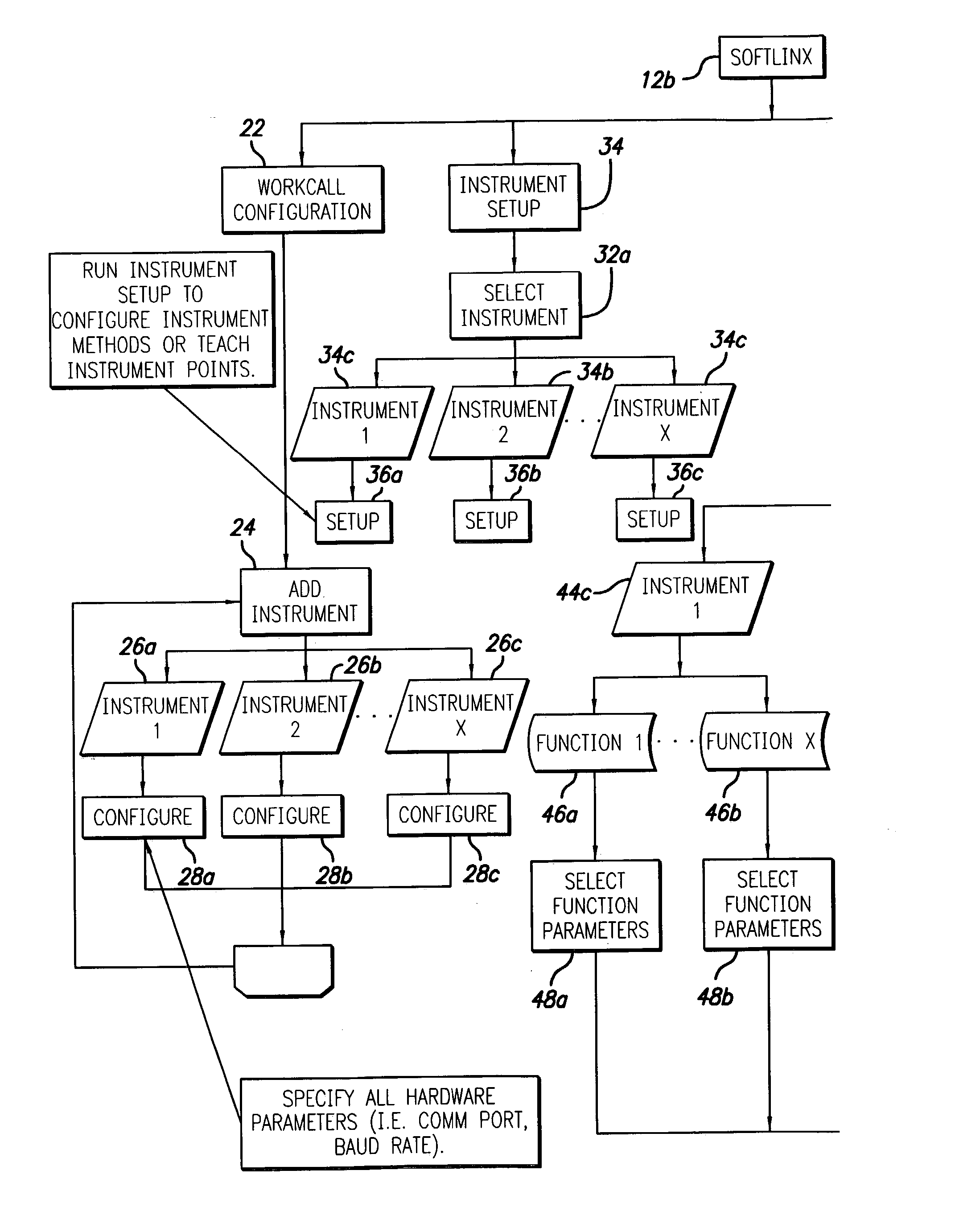
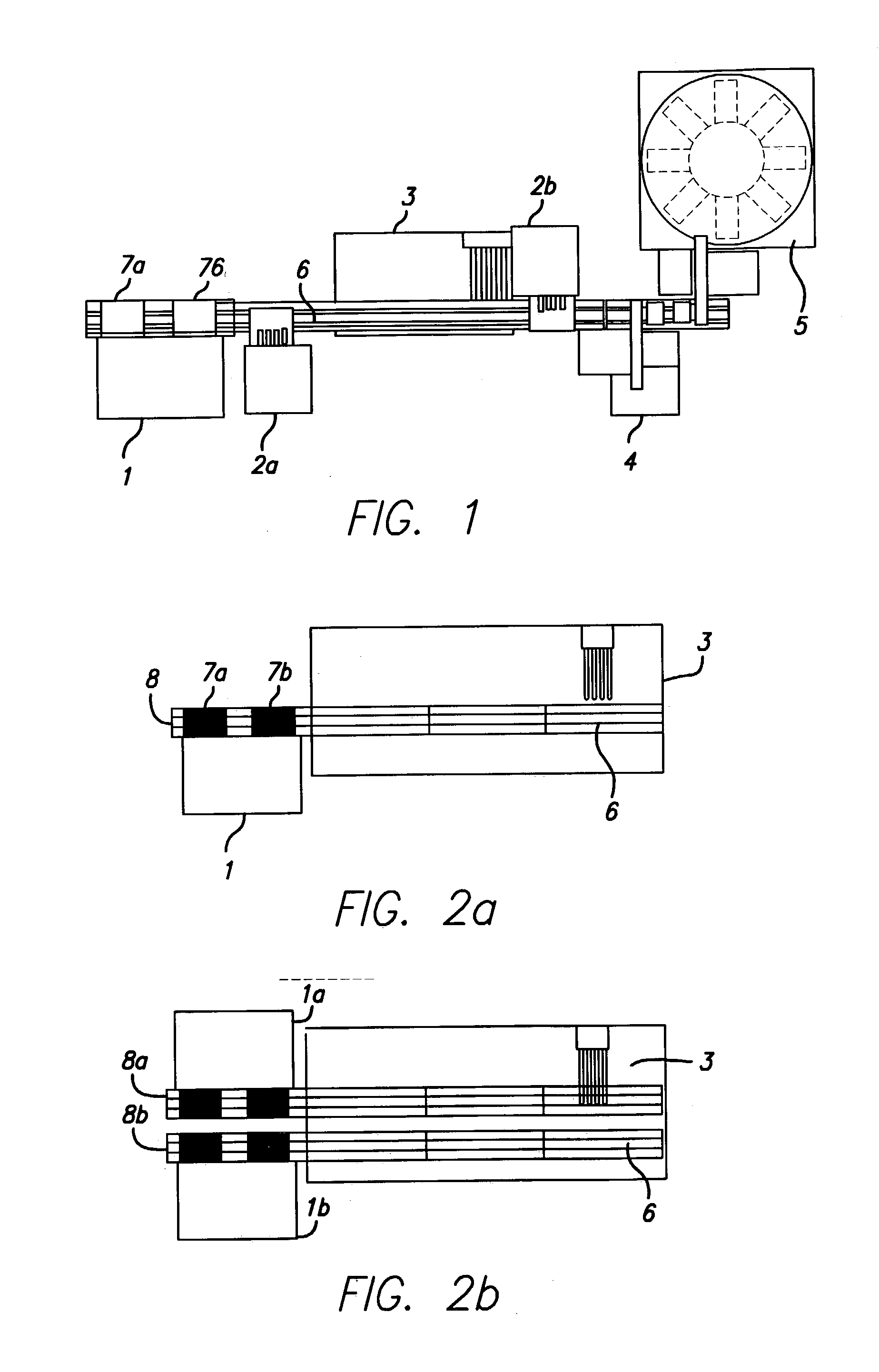
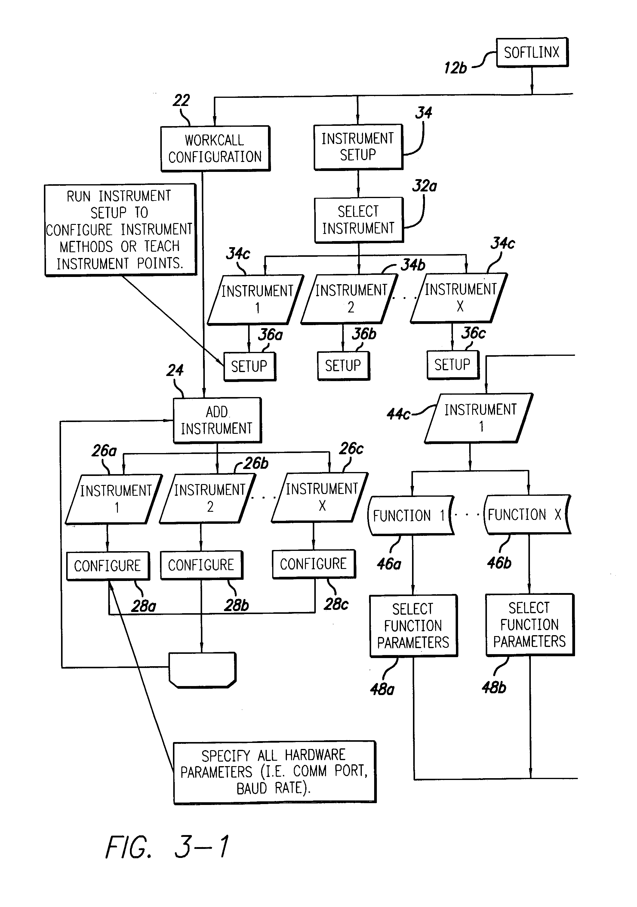
[0042] The system of the present invention is based on a modular, high-speed conveyor system that is connected to basic system components, such as stackers or stack links, and to other lab automation devices. The present invention provides an easy way to build a high-speed, high-capacity lab automation workcell that is configured for ...


PUM

PropertyMeasurementUnit
timeaaaaaaaaaa
timeaaaaaaaaaa
timeaaaaaaaaaa

Abstract

This invention discloses a system and method useful in moving labware between laboratory devices, such as liquid handlers, readers, washers, dispensers, sealers, incubators, microarrayers and labeling devices, such a bar code labelers, to aid in automation of laboratory tasks and assay procedures. Work cells addressing particular laboratory tasks comprise modular components such as stack links, track links, arm links and laboratory devices, such as washers or plate readers. Based upon the required flow of labware movement, the individual modular components are selected and interconnected to create a high-speed work cell. The work cells are easy to configure and setup and permit configuration on available bench top space or within other small spaces, such as laboratory fume hoods. All mechanical and electrical connections between the module components of the work cell are self-contained within the system. A mechanically robust and simple design of the work cell configuration permits reliable walk away automation.

Description

[0001] This application claims priority from the related provisional patent application for Modular Equipment Apparatus and Method for Handling Labware, filed on Jan. 27, 2002, which is hereby incorporated in its reference in its entirety.[0002] 1. Field of the Invention[0003] This invention relates to automated labware handling systems and methods.[0004] 2. Description of the Related Art[0005] Laboratory automation is a term that is used to describe the application of automation and robotics for processes used in scientific labs to improve the quality, efficiency, and relevance of laboratory analysis. Lab automation does not encompass a single function or process. A wide variety of products and processes are used within the lab automation environment. The image that frequently comes to mind when discussing robotic automation is a robot that is accomplishing some type of manufacturing process in place of a human. While robots are indeed an important part of the lab automation enviro...

Claims


Application Information

Patent Timeline
Patent Type & Authority Applications(United States)
IPC IPC(8): G01N35/00G01N35/02G01N35/04
CPCG01N35/0099G01N2035/0465G01N2035/0463G01N35/028
Inventor GILMAN, TOMFARRELLY, PHILIP J.OLSON, CLIFFORD A.NYIRADI, LAJOS
Owner HUDSON CONTROL GROUP
Why Eureka
Try Eureka