Solid oxide fuel cell with enhanced mechanical and electrical properties

a solid oxide fuel cell and mechanical and electrical technology, applied in the direction of cell components, cell component details, electrochemical generators, etc., can solve the problems of inherently high cost of configuration, short path length, and disadvantages of various types of planar sofcs, so as to improve the impact improve the mechanical and electrical properties, and improve the impact resistance and fracture resistance of the electrolyte

Inactive Publication Date: 2003-12-18
UCHICAGO ARGONNE LLC
View PDF13 Cites 68 Cited by
  • Summary
  • Abstract
  • Description
  • Claims
  • Application Information

AI Technical Summary

Benefits of technology

0016] The present invention together with the above and other objects and advantages may best be understood from the following detailed description of the preferred embodiments of the invention illustrated in the drawings, wherein:
0017] FIG. 1 illustrates a solid oxide fuel cell repeat unit in accordance with the preferred embodiment;
0018] FIG. 2 illustrates the solid oxide fuel cell repeat unit of FIG. 1 together with an additional sealing gasket and a gas manifold plate forming a solid oxide fuel cell stack in accordance with the preferred embodiment;
0019] FIG. 3 is a flow chart illustrating exemplary steps for producing the solid oxide fuel cell repeat unit of FIG. 1 in accordance with the preferred embodiment; and
0020] FIG. 4 shows an exemplary repeat unit fabricated in accordance with the process of the present invention.
0021] In accor

Problems solved by technology

This configuration is inherently expensive since the electrolyte and interconnect are applied using multiple high temperature electrochemical vapor deposition steps.
Planar SOFCs have higher power densities since the current flows are perpendicular to the plane of the cell, resulting in short path lengths.
Using metal interconnects, high power densities of 650 mW/cm.sup.2 were achieved in stacks built as described in U.S. Pat. No. 6,296,962 The various types of planar SOFCs have a major disadvantage.
By nature, ceramic stacks are subject

Method used


Image

  • Solid oxide fuel cell with enhanced mechanical and electrical properties
  • Solid oxide fuel cell with enhanced mechanical and electrical properties
  • Solid oxide fuel cell with enhanced mechanical and electrical properties

Examples


example 2

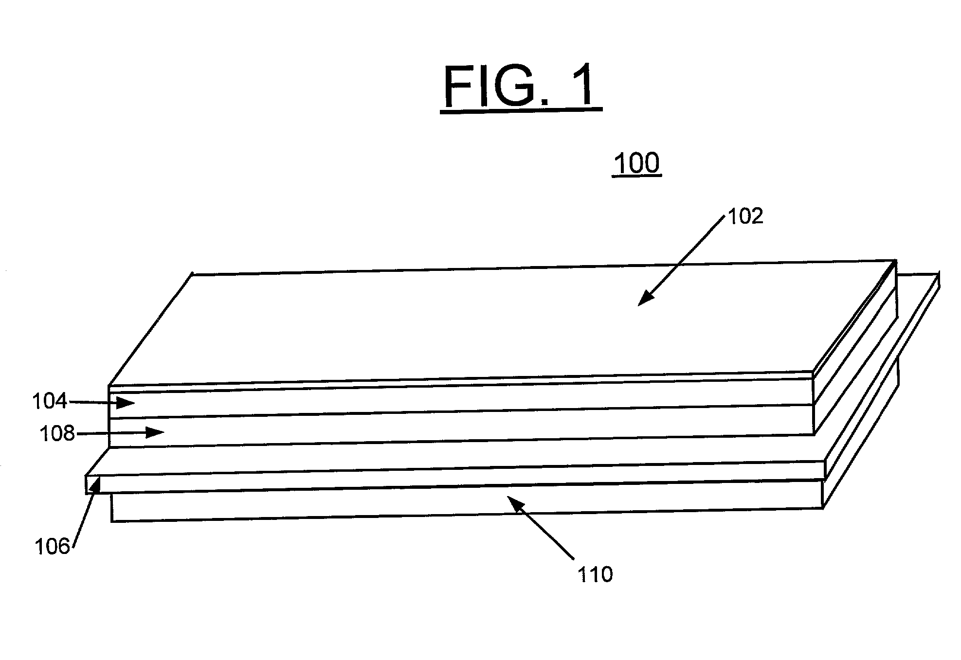
[0041] The mechanical performance of a commercially available anode-supported electrolyte cell (no cathode) in the reduced state has been compared with the invention (repeat unit 100, no cathode). Four samples of the anode-supported cell and three of metal-supported cell were mechanically stressed using the standard 4-point bending test, placing the electrolyte in compression.

[0042] The average strength of the commercially available anode-supported cells was 0.125 GPa. The cells failed catastrophically at this stress resulting in complete fracture of all the samples.

[0043] The repeat units 100 were strained just beyond the elastic yield point of the metal component, at which point, all ceramic layers had cracked and / or delaminated. Two stress-strain events could be observed before the yield point was reached in each of these samples. One event is due to the layers cracking and the second a delamination of the ceramic layers. At present, it is not possible to resolve which event occu...


PUM

PropertyMeasurementUnit
Thicknessaaaaaaaaaa
Temperatureaaaaaaaaaa
Compositionaaaaaaaaaa

Abstract

A solid oxide fuel cell (SOFC) repeat unit includes an oxide electrolyte, an anode, a metallic fuel flow field, a metallic interconnect, and a metallic air flow field. The multilayer laminate is made by casting tapes of the different functional layers, laminating the tapes together and sintering the laminate in a reducing atmosphere. Solid oxide fuel cell stacks are made by applying a cathode layer, bonding the unit into a gas manifold plate, and then stacking the cells together. This process leads to superior mechanical properties in the SOFC due to the toughness of the supporting metallic layers. It also reduces contact resistances in stacking the cells since there is only one physical contact plane for each repeat unit.

Description

[0001] A related U.S. patent application Ser. No. ______, by Michael Krumpelt, Terry A. Cruse, John David Carter, Jules L. Routbort, and Romesh Kumar and assigned to the present assignee is being filed on the same day as the present patent application entitled "COMPOSITIONALLY GRADED METALLIC PLATES FOR PLANAR SOLID OXIDE FUEL CELLS".[0003] The present invention relates to solid oxide fuel cells (SOFCs), and more particularly, relates to an improved planar solid oxide fuel cell having improved mechanical strength and electrical properties and a method of making this improved solid oxide fuel cell.DESCRIPTION OF THE RELATED ART[0004] Fuel cells are conversion devices that generate electricity through the electrochemical oxidation of a fuel. Solid Oxide Fuel Cells (SOFCs) are based on an oxygen-ion conducting ceramic electrolyte, such as zirconium oxide, cerium oxide, or lanthanum gallate. Oxygen is supplied continuously to the cathode where it is dissociated into oxygen ions. The ion...

Claims


Application Information

Patent Timeline
IPC IPC(8): H01M8/02H01M8/12
CPCH01M8/0206H01M8/0228Y02E60/525H01M8/1226Y02E60/521H01M8/1213Y02E60/50
Inventor CARTER, JOHN DAVIDBAE, JOONG-MYEONCRUSE, TERRY ALANRALPH, JAMES MICHAELKUMAR, ROMESHKRUMPELT, MICHAEL
Owner UCHICAGO ARGONNE LLC
Why Eureka
Try Eureka