Electrochemical cell and bipolar assembly for an electrochemical cell

a technology of electrochemical cells and electrochemical cells, applied in the direction of cell components, cell component details, electrochemical generators, etc., can solve the problems of unacceptably low corresponding power-to-weight ratio, large stack of assembled electrochemical cells, and large stack of weigh

Inactive Publication Date: 2003-12-18
LYNNTECH
View PDF81 Cites 48 Cited by
  • Summary
  • Abstract
  • Description
  • Claims
  • Application Information

AI Technical Summary

Benefits of technology

[0016] In still a further embodiment, the gas barrier may include a polymer that promotes, or at least permits, the flow of water through the barrier while preventing the passage of gases. Accordingly, water produced at the cathode, and normally rejected in the exhaust, passes through the barrier where it humidifies the fuel being consumed. This is advantageous because it promotes the full humidification of the PEM membrane, which minimizes its resistance to proton flow. A moisture transfer capability like this can be achieved by utilizing a single phase polymer capable of absorbing substantial amounts of water or by producing a porous barrier having pores filled with such a polymer or with another substance that promotes the transfer of water. Examples of polymers that absorb or conduct moisture include perfluorosulfonic acids (such as Nafion), sulfonated polystyrene, sulfonated trifluorostyrene, polyacrylamides, and similar polymers. The gas barrier may also be made from a polymer blend, where one or more of the polymer components in the blend permits the passage of water through the composite. Alternatively, the water conducting polymer in a blend may be replaced with any other water conducting material, such as a hydrophilic inorganic material like hydrous silica or alumina.
[0025] Furthermore, the posts may be either solid or porous. With any given material a solid post will have the highest electrical conductivity, but it will also be the heaviest, while a porous post will reduce the weight, with some loss of conductivity. These factors must be weighed in the development of any design. If porous posts are selected, then provisions must be made to insure that the post does not present a potential leak between fuel and oxidizer. This provision can be the use of a water conducting filler, as described above, or it can be a barrier produced by sealing the pores in all or part of the post with a non-water conducting filler. In addition, a porous post fabricated with closed cell porosity will provide its own barrier. However, in balancing the competing interests of high electronic conductivity and low weight of the posts, it is perhaps most import that the posts have high electronic conductivity.

Problems solved by technology

An assembled electrochemical cell stack can become quite large and heavy with most of the weight being associated with the bipolar plate / flow field assemblies.
A well-known challenge to broad usage of PEM fuel cell stacks is that the weight of the stack can become so great that the corresponding power-to-weight ratio becomes unacceptably low.
While these reduced-weight bipolar plate / flow field assemblies have resulted in electrochemical fuel cell stacks having good power-to-weight ratios when the current densities are greater than 400 mA / cm.sup.2, these designs are not as effective to provide efficient fuel cell stacks when the operating pressure of the reactants is low, such as in a fuel cell using ambient air on aircraft flying at high altitudes.
For example, when the gas barrier is not electronically in series between the posts and the adjacent cells, the benefits of having an electronically conducting gas barrier are substantially limited to providing lateral conductivity to the bipolar assembly.
When the current collector covers the entire active surface of the electrode, there may be a decrease in the ability of the gas to diffuse to the electrocatalyst.

Method used


Image

  • Electrochemical cell and bipolar assembly for an electrochemical cell
  • Electrochemical cell and bipolar assembly for an electrochemical cell
  • Electrochemical cell and bipolar assembly for an electrochemical cell

Examples


Embodiment Construction

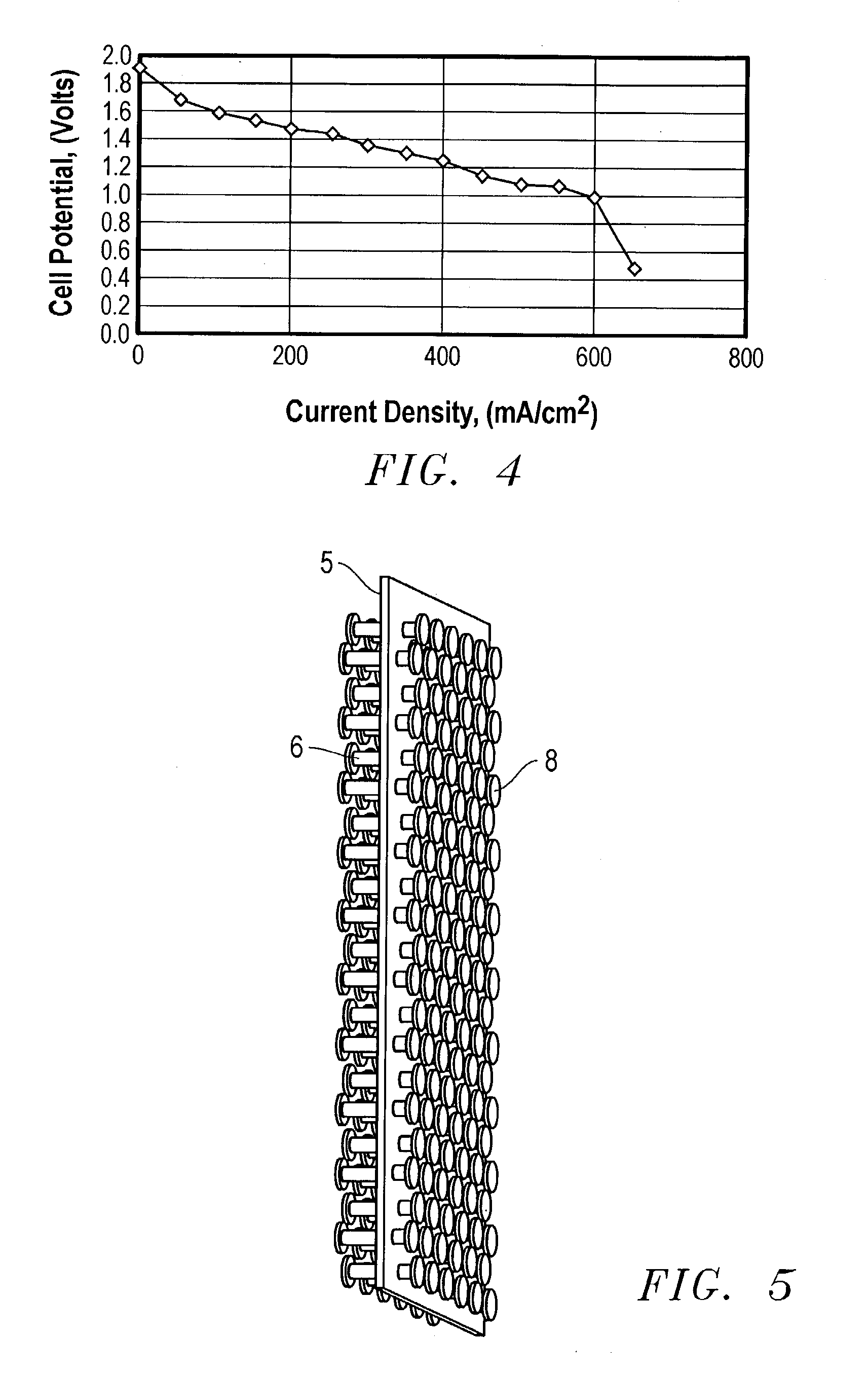
[0065] A bipolar assembly having a post-type flow field was fabricated. The bipolar assembly was fabricated using two 15 mil (0.38 mm) thick gold plated titanium gas barrier sheets, two flow field frames fabricated from Kynar.TM. polymer to be used with the air and hydrogen flow fields, and a high density polyethylene frame for the cooling flow field. The posts consisted of 1 / 8 inch thick carbon spectroscopy rods cut to the correct length. The frames were bonded to the gas barriers with 5 mil (0.127 mm) thick acrylic double-sided tape from 3M.TM..

[0066] Thirty-six evenly spaced 1 / 8 inch holes were drilled into the separator plates in the area of the flow fields. These plates were aligned and sealed to the cooling flow field frame with the double-sided tape. The hydrogen and air flow field frames were then sealed to the separator plates with the same double-sided tape. The spectroscopy rods were cut up into short pieces to match the thickness of the bipolar assembly. The rods were in...


PUM

PropertyMeasurementUnit
current densitiesaaaaaaaaaa
pressuresaaaaaaaaaa
distanceaaaaaaaaaa

Abstract

A bipolar assembly for use in electrochemical cell stacks, especially stacks operated at low pressure. The bipolar assembly is lightweight and provides a "post-type" flow field that operates with a low pressure drop. The bipolar assembly comprises a gas barrier having an array of electronically conducting posts disposed approximately perpendicular to the gas barrier. Each end of the posts is in electrical communication with the surface of an electrode. Because the bipolar assembly separates a cathode from an anode, the posts contact an anode electrode on one end and a cathode electrode on the other end. The posts provide current conduction through the stack as well as provide the flow fields for the electrochemical reactants. Optionally, the bipolar assembly may contain cooling fluid channels formed by adding additional gas barriers to the bipolar assembly. The space between the gas barriers form a channel through which cooling fluids may be circulated.

Description

[0001] 1. Field of the Invention[0002] The present invention provides an electrochemical cell and subassembly for an electrochemical cell, particularly electrochemical stacks.[0003] 2.Description of the Related Art[0004] Electrochemical cells include, but are not limited to, fuel cells, electrolysis or electrolyzer cell, electrochemical synthesis cells, electrochemical oxygen concentrators (also known as electrochemical oxygen pumps), and electrochemical hydrogen concentrators (also known as electrochemical hydrogen pumps). Electrochemical cell stacks are made up of individual electrochemical cells that are connected in series. The structure and operation of these electrochemical cells have many common aspects, which will be discussed herein in the context of a fuel cell stack.[0005] The primary components of a proton exchange membrane (PEM) fuel cell stack are the membrane and electrode assemblies (MEAs), gas diffusion layers, and bipolar plate / flow field assemblies. These componen...

Claims


Application Information

Patent Timeline
Patent Type & Authority Applications(United States)
IPC IPC(8): H01M2/08H01M8/02
CPCH01M8/0206H01M8/0213H01M8/0221H01M8/0223H01M8/023Y02E60/50H01M8/0241H01M8/0247H01M8/0256H01M8/026H01M8/0271H01M8/0232
Inventor CISAR, ALAN J.ANDREWS, CRAIG C.GREENWALD, CHARLES J.MURPHY, OLIVER J.BOYER, CHRISYALAMANCHILI, RATTAYASALINAS, CARLOS E.
Owner LYNNTECH
Why Eureka
Try Eureka