Check patentability & draft patents in minutes with Patsnap Eureka AI!

Method for making fine prints from oscillations in fresnel diffraction patterns in ultra high resolution lithography

Inactive Publication Date: 2004-01-15
BOURDILLON ANTONY J
View PDF4 Cites 4 Cited by
  • Summary
  • Abstract
  • Description
  • Claims
  • Application Information

AI Technical Summary

Benefits of technology

[0019] Moreover the fabrication of masks is simplified because the clear mask features are also significantly enlarged owing to larger selected demagnification factor. Whereas, in the prior art, only one mask feature was printed from each clear mask feature; my method of Fresnel oscillations employs multiple prints with value for increased printing speed and wafer throughput.
[0020] More generally, by using oscillations in Fresnel diffraction, finer patterns can be printed, than in UHRL and MASC, while retaining the general advantages of UHRL.

Problems solved by technology

This minimization of interference limited the demagnification of features.
The consequent limitation in demagnification resulted in limitations in the size of mask-wafer gaps.
The limitation in demagnification had the second consequence that, for given print feature sizes, clear mask features had to be unnecessarily small, and this is a second critical parameter in the printing of fine features.

Method used


Image

  • Method for making fine prints from oscillations in fresnel diffraction patterns in ultra high resolution lithography
  • Method for making fine prints from oscillations in fresnel diffraction patterns in ultra high resolution lithography
  • Method for making fine prints from oscillations in fresnel diffraction patterns in ultra high resolution lithography

Examples


embodiment

[0089] Operation--main embodiment

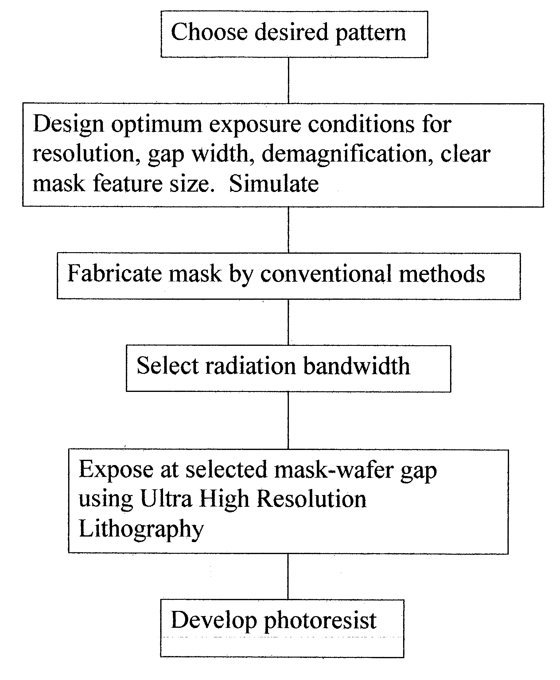
[0090] My method using Fresnel oscillations is employed within the context of UHRL. For a given wavelength, or range of wavelengths, and given clear mask feature size, the mask-wafer gap is set so that the Fresnel pattern at the resist contains selected oscillations. For the simplest case of a slit mask feature, the first oscillation pattern occurs when the dimensionless slit width, .DELTA..nu..about.3.8. A development level is chosen so that fine oscillation lines within the Fresnel pattern are printed. Typically the oscillation lines have a finer resolution than for UHRL employed near CC.

[0091] I show how to select oscillation patterns in Fresnel diffraction, whether by using single exposures or by using multiple exposures. By using the adapted Cornu spiral or by other simulations, I show how to optimise the exposures. The methods extend to the superposition of exposures and this is particularly applicable to developing fine two-dimensional pattern...


PUM


Abstract

This method of Fresnel oscillations takes advantage of oscillation effects within Fresnel patterns to produce finer resolution than can be printed in the prior art. Selected patterns are printed by selecting the mask-wafer gap for a given wavelength, or range of wavelengths, and given mask feature size. Following the principles of the coherence and with an optimization of bandwidth, the method of Fresnel oscillations employs paradigms or simulations in mask shapes to print specified patterns. By these methods, exposure times and throughput are optimized, consistent with required resolution in printing. Mask-wafer gaps and clear mask feature sizes are kept large. With multiple exposures, fine oscillation patterns in two dimensions can be printed with demagnification factors down to 20X the size of clear mask features.

Description

[0001] The invention uses the transmission of previous patent No. 6,383,697, Ultra high resolution lithographic imaging and printing and defect reduction by exposure near the critical condition using Fresnel diffraction.,[0002] and of co-pending application, Ser. No. 10 / 041304, Mask shaping using temporal and spatial coherence in ultra high resolution lithography.[0003] This application is entitled to the benefit of Provisional Patent Application Ser# 60 / 395298 filed Jul. 12, 2002.[0004] 1. Field of Invention[0005] This invention applies to the field of micro-lithography and the application of microlithography as a tool in development and production of micro-electronic devices, integrated circuits, and micro-machines.[0006] 2. Discussion of Prior Art[0007] In Ultra High Resolution Lithography (UHRL, U.S. Pat. No. 6,383,697), printing is achieved by demagnifying clear mask features without the use of either lenses or mirrors between the mask and a resist coated wafer. The mask is pla...

Claims


Application Information

Patent Timeline
IPC IPC(8): G03F7/20
CPCG03F7/70325G03F7/70466G03F7/7035
Inventor BOURDILLON, ANTONY J.
Owner BOURDILLON ANTONY J
Features
  • R&D
  • Intellectual Property
  • Life Sciences
  • Materials
  • Tech Scout
  • Unparalleled Data Quality
  • Higher Quality Content
  • 60% Fewer Hallucinations
Learn More