[0018] According to the present disclosure, advantageous filter elements may be provided that offer superior filtration performance including improved flow for a given filter
cartridge size / design, the latter being achieved through the selection of
support materials that act cooperatively to improve total flow.
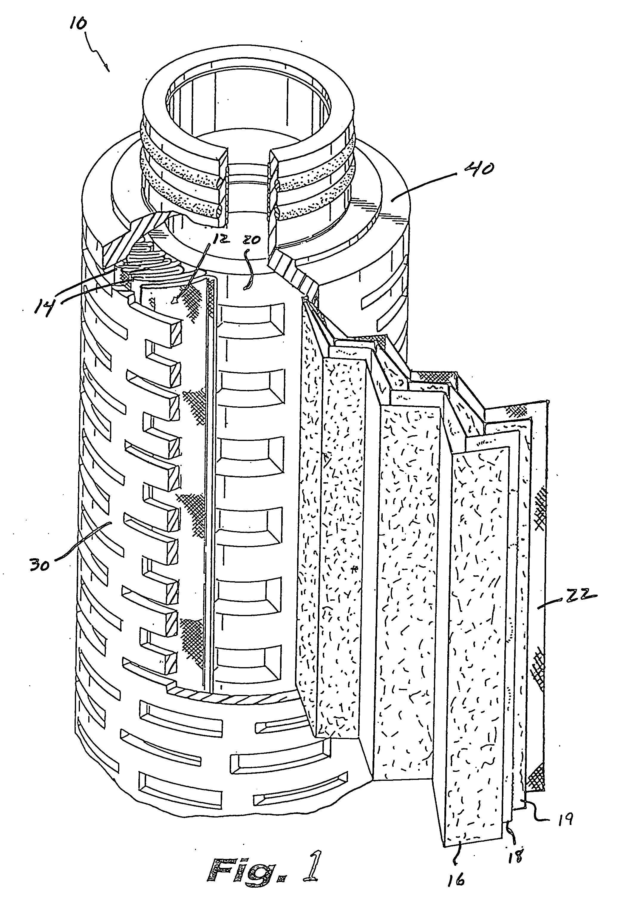
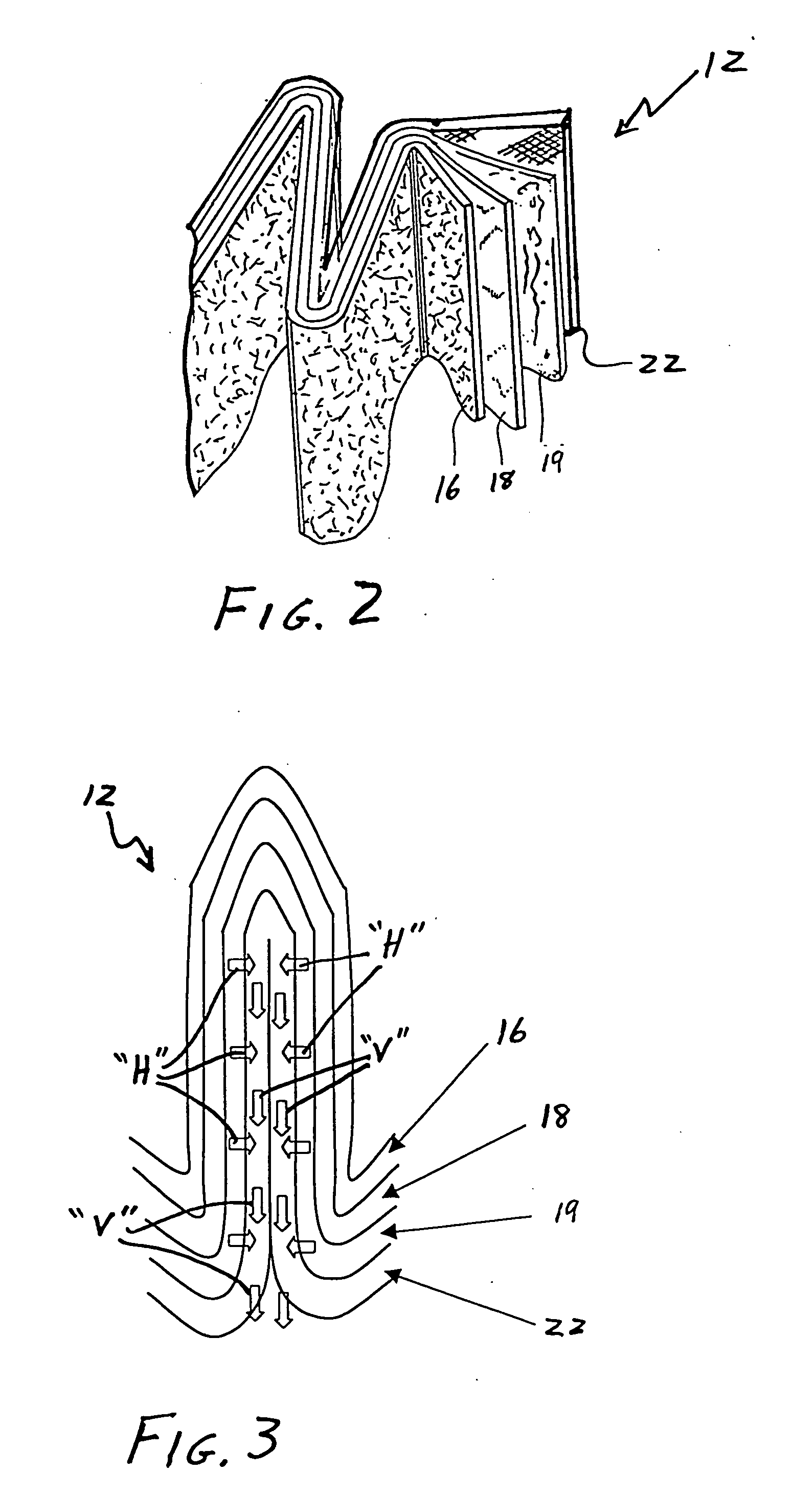
[0022] More particularly, the multi-layer downstream pleat support includes a first downstream support layer and a second downstream support layer. The first downstream support layer is interposed between the filtration media and the second downstream support layer and is fabricated so as to minimize points of surface contact with the filtration media, thereby enhancing fluid flow away from the filtration media. The first downstream support is fabricated from a material that contacts the membrane in as few locations as possible so as to allow the fluid, whether it be liquid or gas, to egress from the filtration media and into the second downstream support layer located just below. Suitable materials for use in fabricating the first downstream support layer are non-woven materials characterized by high air permeability, low thickness, high strength, low
fiber diameter and / or a relatively soft feel to prevent abrasion of the filtration media. Preferred examples of materials for fabricating the first downstream support
layers are
polypropylene or polyesters. In an alternative embodiment, the first downstream support layer can be fabricated of a nonwoven material that is laminated to the filtration media. However, it is generally preferred to provide the first downstream support layer in non-laminated juxtaposition relative to the filtration media, thereby improving flow through the first support layer and the filtration media, e.g., by as much as 3 to 5%.
[0023] According to the present disclosure, the second downstream support layer is in contact with the first downstream support layer and is fabricated so as to facilitate lateral fluid flow. Preferably, the second downstream support layer is fabricated from an extruded apertured
film material, and preferably an apertured
film material having rib(s) formed on one side. The rib(s) advantageously maintain a gap when the pleated filtration media is folded onto itself, thereby greatly improving lateral fluid flow.
[0024] The inventors herein have established (infra) that eliminating either the first or the second downstream support layer will degrade the performance of the filter. The first downstream support layer, which is typically fabricated from a nonwoven material, does not provide optimum lateral flow. Likewise, the extruded apertured film would disadvantageously effect a sealed contact against the filtration media if placed directly against it, thereby limiting fluid egress from the filtration media to aperture locations. The addition of the support
layers to the
filter design allows an increase in the media area without resorting to different pleat designs, larger geometries or ever thinner supports, despite the fact that the additional support layers effectively add thickness. The relatively thin filtration media is capable of increased packing by pressing the pleats together more closely, but in prior art systems, the increased area associated with tight packing does not result in increased flow because the
support materials are closely pinched together. It has now been found that when multiple downstream support layers are employed, as described in the present disclosure, the higher filtration area will beneficially lead directly to improved flow because the transport of the fluid from the downstream layers to the core will not be impeded. However, even when the filler element is constructed with less filtration area, the construction in accordance with the invention provides improved flow rate and improved flux, i.e., flow per area.
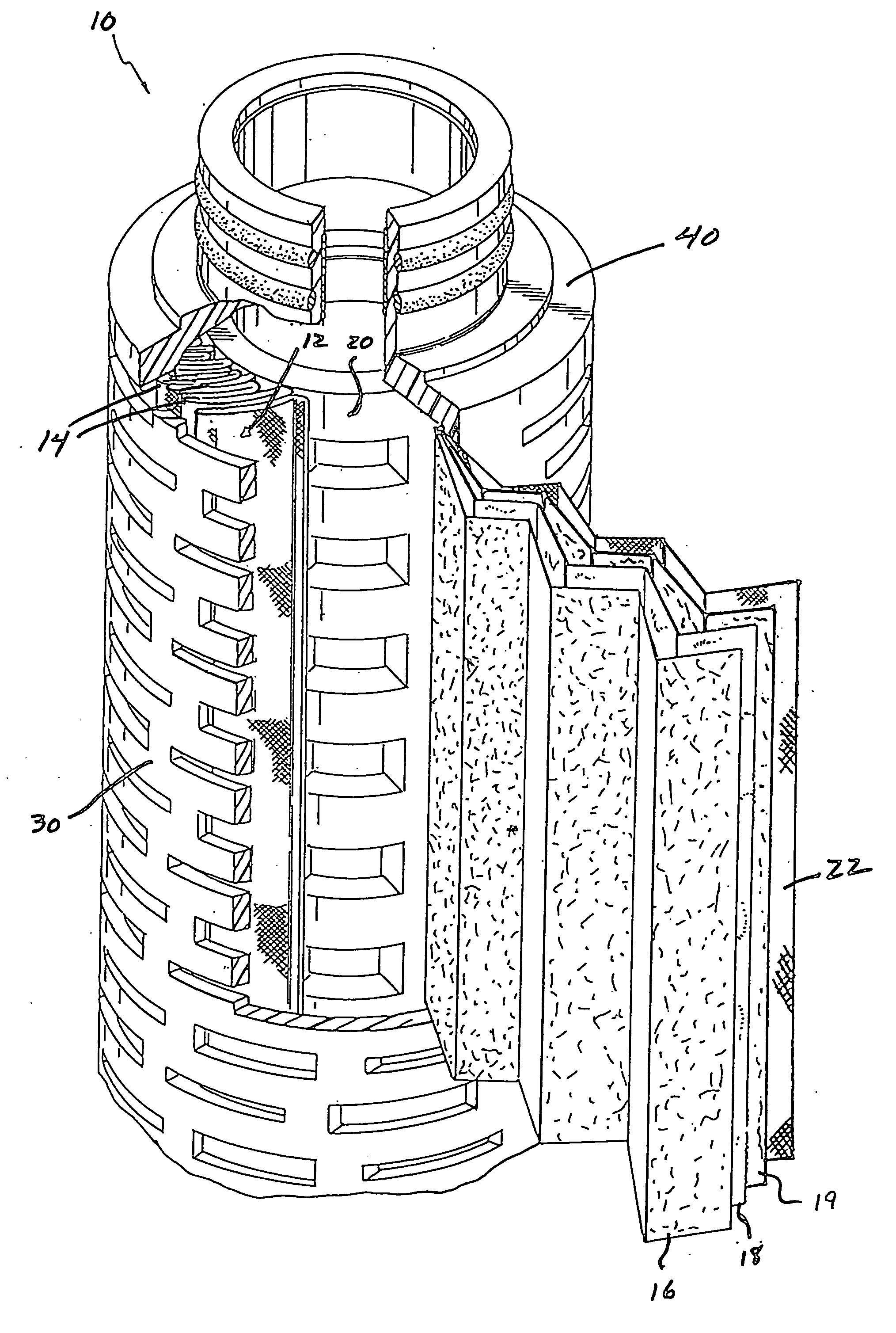
[0026] The disclosed filter elements may be utilized in filter cartridges, preferably cylindrical cartridges although the filter elements may be used to equal
advantage with non-cylindrical filtration devices (planar filtration devices) and non-radial pleat constructions (spiral pleats), to provide enhanced filtration performance, e.g., by way of increased media area and improved flow. An exemplary filter
cartridge according to the present disclosure includes a filter element having a longitudinal axis, an outer periphery and an inner periphery. The filter element typically includes a filtration media, an upstream pleat support positioned upstream from and in contact with said filtration media, and a multi-layer downstream pleat support positioned downstream from said filtration media, as disclosed herein. Exemplary filter cartridges according to the present disclosure also typically include a perforated, preferably cylindrical, cage surrounding the outer periphery of the filter element, a perforated, preferably cylindrical, core surrounded by the inner periphery of the filter element coaxially positional between the core and the cage. The cartridge
assembly is coaxially positioned within the cage. It is necessary to seal the ends of the pleated element to prevent flow from bypassing around the edges. As is well known in the art, this is accomplished through the use of end caps. The end cap must be made of a material which first achieves a flow state so it can envelope the edge of the pleat structure and then harden to make a permanent seal. One typical means of accomplishing this sealing action is through use of a thermomelt material such as
polypropylene,
polyethylene or
polyester, which reaches the melt state through heating and hardens with cooling. An alternate method would be to use a thermoset, such as
epoxy, or a
thermoplastic, such as santoprene, which are in a
liquid state initially but harden upon cure. The term "hard" as used herein is relative as santoprene is an elastomeric material. It is highly preferred that the end caps also embed the cage and core to provide the filter with added rigidity and strength.
[0028] In accordance with an embodiment of the invention, in a separate step the end caps are combined with an adapter element to form a single part that allows the filter element to more easily be fitted into the filter housing.

