Wavelength-selective diffraction element and an optical head device

a diffraction element and wavelength-selective technology, applied in the direction of optical beam sources, disposition/mounting of heads, instruments, etc., can solve the problems of inability to record or reproduce information, inability to select diffraction efficiency, loss of light quantity and reduce signal intensity, etc., to achieve excellent heat resistance and irradiation resistance, the effect of easy change of diffraction efficiency and easy change of wavelength dispersibility

Inactive Publication Date: 2004-05-20
ASAHI GLASS CO LTD
View PDF6 Cites 20 Cited by
  • Summary
  • Abstract
  • Description
  • Claims
  • Application Information

AI Technical Summary

Benefits of technology

[0070] As mentioned above, the case that an organic pigment is contained in the diffraction grating 12 has been explained. However, the same effect is obtainable even in a case that an organic pigment is contained in the filling member 13A.
[0111] As the red pigment, an organic pigment classified into a diketopyrrolopyrrole type, an anthraquinone type, a quinacridone type, a condensed azo type, a perylene type and so on can be used. These organic pigments may be used solely, or a mixture of two kinds or at least three kinds may be used. Among them, the diketopyrrolopyrrole type represented by Pigment Red 254 or the anthraquinone type represented by Pigment Red 177 is preferably used as a red organic pigment for this element because they have excellent durability.

Problems solved by technology

In the first conventional optical head device in which the 3-beam generating diffraction element used for the 3-beam method or the differential push-pull method is used in combination of the two-wavelength semiconductor laser, however, the following problem arises.
As a result, unwanted diffracted lights as stray lights enter into the photodetector, whereby it is impossible to record or reproduce the information.
Further, there is also a problem that the diffraction grating provided to generate three-beams for an incoming light for either optical disk diffracts an incoming light for the other optical disk to produce unwanted diffraction light to thereby cause a loss of light quantity and reduce intensity of signals.
However, the condition of making the optical path difference of an incoming light having a wavelength band to be integer times as much as the wavelength of the incoming light would restrict flexibility in designing the other wavelength, and flexibility in selecting the diffraction efficiency was also limited, and therefore, the disclosed diffraction element was unsatisfactory.
Further, in the case of the second conventional optical head device, namely, when the holographic beam splitter is used in combination of the two-wavelength semiconductor laser having a monolithic structure, the following problem results.
To increase the light receiving surface area causes deterioration of high frequency characteristics whereby a rapid reproduction of an optical disk is difficult.
On the other hand, when light receiving surfaces are formed in the photodetector in order to receive the light having a 650 nm wavelength band and the light having a 790 nm wavelength band, the number of light receiving elements increases twice with the result of a problem that the signal processing circuit becomes complicated.
Accordingly, when the optical path difference is larger or the grating pitch is smaller, these approximation formulas are not applicable.
Since the grating pitch was small as compared with the optical path difference, there was a problem of causing a reduction of the transmittance of a wavelength to be transmitted, due to the above-mentioned resonance.

Method used


Image

  • Wavelength-selective diffraction element and an optical head device
  • Wavelength-selective diffraction element and an optical head device
  • Wavelength-selective diffraction element and an optical head device

Examples


first embodiment

[0124] (First Embodiment of the Optical Head Device)

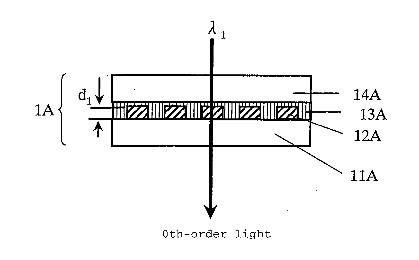
[0125] FIG. 8 shows a first embodiment of the optical head device of the present invention in which the optical head device uses the wavelength-selective diffraction element 1A (FIG. 1) for generating 3 beams usable for a CD, as a wavelength-selective diffraction element. In the optical head device thus constructed, light having a wavelength .lambda..sub.1 emitted from a two-wavelength semiconductor laser 3 (which is formed by unifying a semiconductor laser for emitting a laser light having a wavelength of .lambda..sub.1 for a DVD series optical disk and a semiconductor laser for emitting a laser light having a wavelength .lambda..sub.2 for a CD series optical disk) propagates linearly without being diffracted by the wavelength-selective diffraction element 1A and transmits through a beam splitter 4 to enter into a collimator lens 5 where the laser light is rendered to be a parallel beam.

[0126] Then, the parallel beam is focused on...

second embodiment

[0133] (Second Embodiment of the Optical Head Device)

[0134] FIG. 10 shows a second embodiment of the optical head device of the present invention in which the optical head device uses the wavelength-selective diffraction element 1C as a holographic beam splitter. In the optical head device thus constructed, light having a wavelength .lambda..sub.1 emitted from a two-wavelength semiconductor laser 3 for emitting light having wavelength .lambda..sub.1 and wavelength .lambda..sub.2 enters into the holographic splitter where about 70% of the entering light is transmitted, and it is rendered to be a parallel beam by a collimator lens 5. Then, the parallel beam is focused on an information recording track of an optical disk 7 (DVD series) by means of an objective lens 6. The light reflected by the optical disk 7 transmits again through the objective lens 6 and the collimator lens 5 to enter into the wavelength-selective holographic beam splitter. About 10% of light diffracted by the beam ...

eighth embodiment

[0138] (Eighth Embodiment of the Wavelength-Selective Diffraction Element)

[0139] The wavelength-selective diffraction element 1H of this embodiment shown in FIG. 16 comprises the wavelength-selective diffraction element used in the first embodiment provided that the diffraction grating is formed only in its peripheral portion. The wavelength-selective diffraction element 1H is a diffraction element provided with a transparent substrate 11H having a front surface on which a diffraction grating 12H having a concavo-convex portion for a grating (which is comprised of a concavo-convex member) is formed and a filling member 13H filled in the space. A transparent substrate 14H is formed thereon to protect the filling member 13H.

[0140] The refractive index of the diffraction grating 12H is equal to that of the filling member 13H with respect to light having a wavelength .lambda..sub.1 and the refractive index of the diffraction grating 12H is different from that of the filling member 13H w...


PUM

PropertyMeasurementUnit
wavelength bandaaaaaaaaaa
angleaaaaaaaaaa

Abstract

An optical head device having an optical element capable of transmitting without diffracting light having a wavelength emitted from a two-wavelength semiconductor laser and capable of diffracting light having another wavelength, to provide high utilization efficiency of light in a stable manner. For this purpose, a wavelength-selective diffraction element 1A comprising a transparent substrate having a front surface on which a grating having a periodically recessed and projected shape in cross section is formed and a filling member 13A filled in the concavo-convex portion 12A of the grating wherein the concavo-convex portion of the grating is provided with an organic pigment having the absorption edge of light in a region having a shorter wavelength than the wavelength lambda1, and the concavo-convex member and the filling member have the same refractive index with respect to either one of light having a wavelength lambda1 and light having a wavelength lambda2, and they have different refractive indices with respect to the other light having a wavelength, is disposed between the light source and the objective lens of the optical head device.

Description

[0001] The present invention relates to a wavelength-selective diffraction element and an optical head device. In particular, it relates to a wavelength-selective diffraction element adapted to receive light having two different wavelengths and an optical head device mounting thereon such wavelength-selective diffraction element.[0002] There have been used various optical head devices for recording information in the information recording surface an optical recording medium such as an optical disk such as CD, DVD or the like, or a magneto-optical disk (hereinbelow, referred to as "the optical disk" as a whole), or reproducing the information in the information recording surface. A diffraction element is used for many purposes in such optical head device.[0003] In the optical head device, the optical disk is rotated while a laser light is focused on a track formed in the information recording surface of the optical disk. Therefore, it is necessary not to deviate focused laser beams f...

Claims


Application Information

Patent Timeline
Patent Type & Authority Applications(United States)
IPC IPC(8): G02B5/18G02B5/20G11B7/1353G02B27/10G11B7/00G11B7/09
CPCG02B5/1866G02B5/203G02B27/1006G02B27/1086G11B2007/0006G02B27/145G11B7/127G11B7/1353G02B27/144G02B5/18
Inventor GOTO, RYUICHIROHOTAKA, HIROKIOOI, YOSHIHARUNOZAWA, REIKOSHIMODAIRA, NORIAKIMURAKAMI, RYOTA
Owner ASAHI GLASS CO LTD
Why Eureka
Try Eureka