
Optically variable security devices

Inactive Publication Date: 2004-05-27
PHILLIPS ROGER W +3
View PDF57 Cites 104 Cited by
  • Summary
  • Abstract
  • Description
  • Claims
  • Application Information

AI Technical Summary

Benefits of technology

[0018] It is a primary object of the invention to provide a security article having color shifting properties which increases the difficulty of counterfeiting in a variety of applications.

Problems solved by technology

Various ways to counteract these methods have been explored but none of the countermeasures, taken alone, has been found to be an effective deterrent.
A further problem with security holograms is that it is difficult for most people to identify and recollect the respective images produced by such holograms for verification purposes.
The ability of the average person to authenticate a security hologram conclusively is compromised by the complexity of its features and by confusion with decorative diffractive packaging.
Thus, most people tend to confirm the presence of such a security device rather than verifying the actual image.
Unfortunately, this added complexity does not confer added security because this complex imagery is hard to communicate and recollection of such imagery is difficult, if not impossible, to remember.

Method used


Image

  • Optically variable security devices
  • Optically variable security devices
  • Optically variable security devices

Examples


example 2

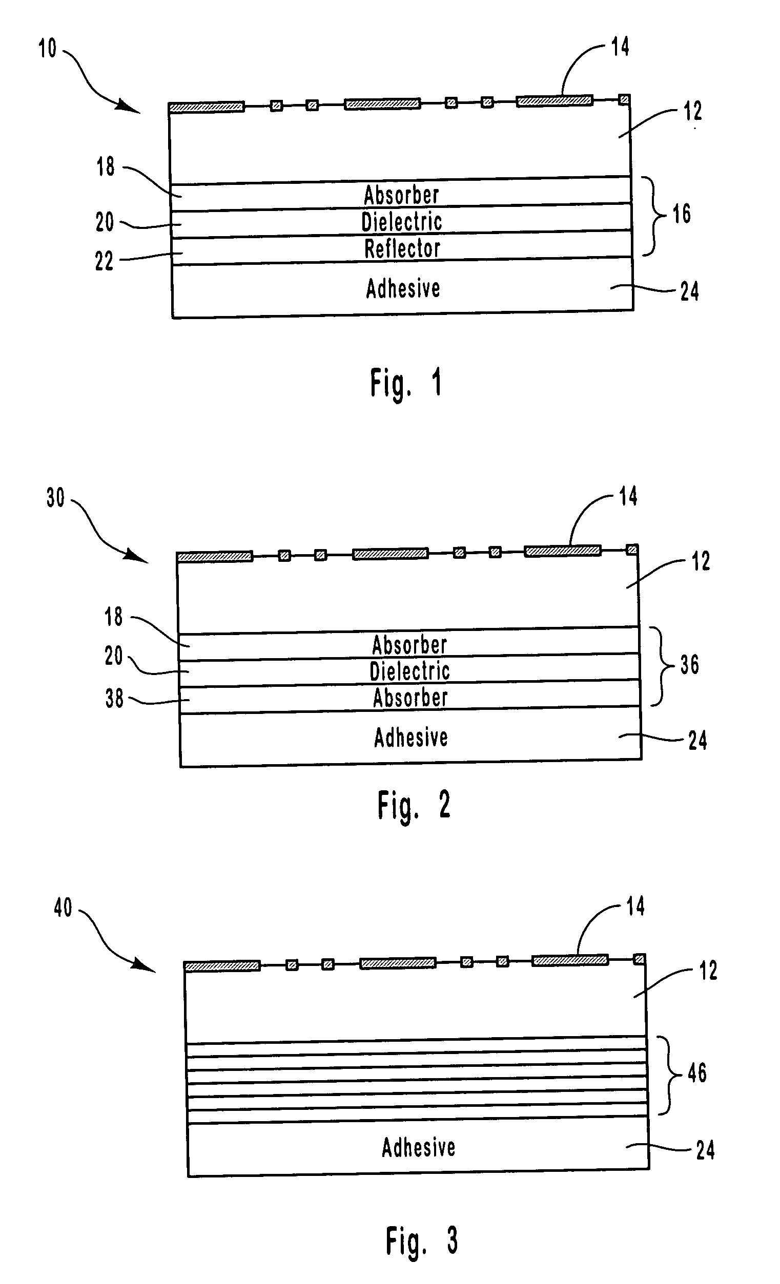
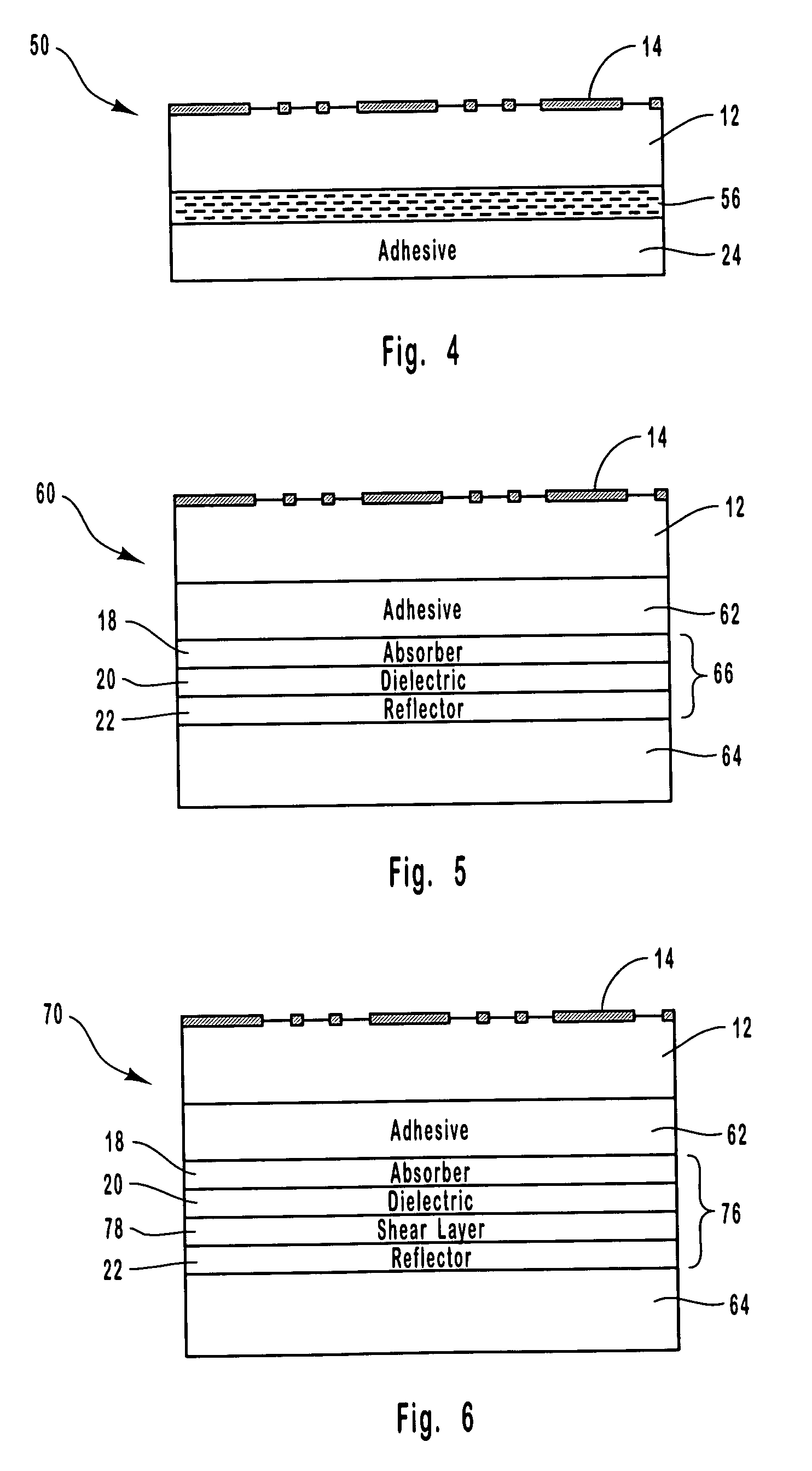
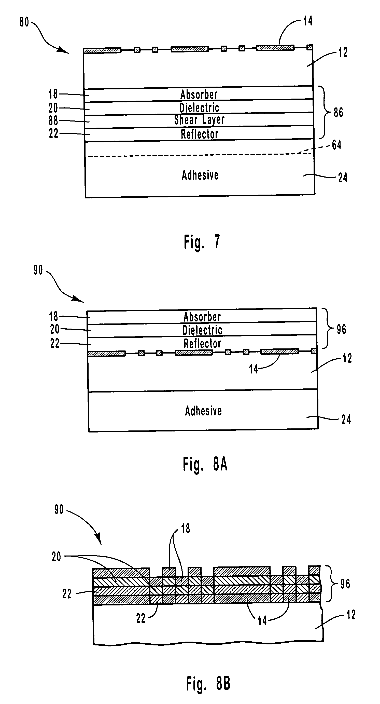
[0115] A color shifting optical coating having a three-layer design was formed on an embossed transparent film to produce a security article. The optical coating was formed on the flat surface of the transparent film on the side opposite from the embossed surface. The optical coating was formed by depositing an absorber layer composed of chromium on the flat surface of the transparent film, depositing a dielectric layer composed of magnesium fluoride on the absorber layer, and depositing a reflector layer of aluminum on the dielectric layer.

[0116] Alternatively, the aluminum layer can be deposited so that it is essentially transparent. This would allow printed information on an object to be read underneath the optical coating. Further, the reflector layer can alternatively be composed of a magnetic material. Such a magnetic feature in the color shifting component when added to the holographic component would give three independent security features to the security article.

[0117] The...

example 3

[0118] A security article was formed by laminating a laser imaged optical coating structure to an embossed substrate according to the present invention. The security article included four main parts: 1) A laser ablated image, 2) a laser ablated bar code or serial number, 3) a multilayer color shifting thin film, and 4) a holographic image.

[0119] The color shifting thin film was deposited in a vacuum roll coater onto a clear polyester (PET) substrate that was 1 mil thick. The thin film was formed by depositing a metal layer of aluminum on the substrate, followed by a dielectric layer composed of magnesium fluoride being deposited on the metal layer, and an absorber layer composed of chromium being deposited on the dielectric layer. Thereafter, the thin film was subjected to laser ablation using a laser diode imaging system based on the Heidelberg Quickmaster printing system to provide digital encoding. The imaging system used a high-resolution diode laser array with a spot size of ap...

example 4

[0121] The security article of Example 3 was subjected to various tests to measure its optical performance, which are described as follows.

[0122] A. Instrumentation and Sample Orientation

[0123] A Zeiss GK / 311M goniospectrophotometer using a xenon flash lamp with angle adjustable fiber optics for both illumination and reflectance was used to characterize the security article. Three types of viewing conditions were examined, with the geometries utilized shown in FIGS. 17A and 17B. These viewing conditions included: a) set angle of illumination at 45 degrees, with the angles of measurement being 5 degree increments from 65 through 155 degrees (FIG. 17A); b) off-gloss, with the angles of illumination being 5 degree increments from 25 through 75 degrees and the angles of measurement being 5 degree increments from 100 through 150 degrees (FIG. 17B); and c) on-gloss (specular), with the angles of illumination being 5 degree increments from 25 through 80 degrees and the angles of measuremen...


PUM

PropertyMeasurementUnit
Lengthaaaaaaaaaa
Lengthaaaaaaaaaa
Lengthaaaaaaaaaa

Abstract

A security article includes a light transmissive substrate having a first surface and an opposing second surface, with the first surface having an optical interference pattern such as a holographic image pattern or an optical diffraction pattern thereon. A color shifting optical coating is formed on the substrate such as on the interference pattern or on the opposing second surface of the substrate, with the optical coating providing an observable color shift as the angle of incident light or viewing angle changes. Various processes can be utilized to form the security article, such as vacuum coating processes, lamination, laser scribing, and laser imaging. The security article can be affixed to a variety of objects through various attachment mechanisms, such as pressure sensitive adhesives or hot stamping processes, to provide for enhanced security measures such as anticounterfeiting.

Description

[0001] This is a divisional application of U.S. application Ser. No. 09 / 489,250, filed Jan. 21, 2000 and entitled "Optically Variable Security Devices," which is incorporated herein by reference, and to which priority is claimed.[0002] This application is related to U.S. application Ser. No. 09 / 351,102, filed Jul. 8, 1999, and entitled "Diffractive Surfaces with Color Shifting Backgrounds."[0003] This application is related to U.S. application Ser. No. 10 / 688,357, filed Oct. 17, 2003, and entitled "Security Articles having Diffractive Surfaces and Color Shifting Backgrounds."[0004] 1. The Field of the Invention[0005] The present invention is related generally to thin film optical coatings for use in producing security articles. More specifically, the present invention is related to the production of diffractive surfaces such as holograms or gratings having color shifting or optically variable backgrounds which can be used as security articles in a variety of applications.[0006] 2. T...

Claims


Application Information

Patent Timeline
IPC IPC(8): B42D25/30B42D15/00B42D15/10B42D25/328G02B5/18G02B5/28G03H1/18G03H1/26
CPCB32B27/36Y10T428/25G03H1/0244G03H1/0252G03H1/0256G03H2250/10G03H2250/34G03H2250/36G03H2250/40G03H2250/42B42D25/29B42D25/328B42D25/355B42D25/00Y10T428/24942Y10T428/24479B42D2035/24B42D25/36B42D25/378B42D25/41B42D25/425B42D25/47B42D25/30B42D25/21B42D25/23B42D25/24B42D25/455
Inventor PHILLIPS, ROGER W.BONKOWSKI, RICHARD L.HIGGINS, PATRICK K.MARKANTES, CHARLES T.
Owner PHILLIPS ROGER W
Learn More