Downhole data transmission system

Inactive Publication Date: 2004-06-03
INTELLISERV
99 Cites 154 Cited by

AI-Extracted Technical Summary

Problems solved by technology

Naturally, these systems have the disadvantage that the data is not available to the drill operator in real time.
The chief drawbacks to this mud pulse system are that the data rate is slow, i.e. less than 10 baud; the system is complex and expensive; the results can be inconsistent; and the range of performance can be limited.
A decided drawback of such systems is the fact that the downhole environment is quite harsh.
The drilling mud pumped through the drill string is abrasive and typically has a high salt cont...

Benefits of technology

0113] In the most preferred embodiment of the invention, any source of information along the drill string, such as the bit sub illustrated in FIG. 18, or a repeater, as described in the previous paragraph, may constitute an addressable node in a Drilling Local Area Network (DLAN). Preferably every repeater and every data sub manufactured in the world will be identified with a unique address. This address might be characterized by programming a programmable memory chip in the tool with a code having a sufficient number of bits to encompass all tools that might ever be connected to any DLAN comprising the transmission line of the pre...

Abstract

A system for transmitting data through a string of downhole components. In one aspect, the system includes first and second magnetically conductive, electrically insulating elements at both ends of the component. Each element includes a first U-shaped trough with a bottom, first and second sides and an opening between the two sides. Electrically conducting coils are located in each trough. An electrical conductor connects the coils in each component. In operation, a varying current applied to a first coil in one component generates a varying magnetic field in the first magnetically conductive, electrically insulating element, which varying magnetic field is conducted to and thereby produces a varying magnetic field in the second magnetically conductive, electrically insulating element of a connected component, which magnetic field thereby generates a varying electrical current in the second coil in the connected component.

Application Domain

Technology Topic

Image

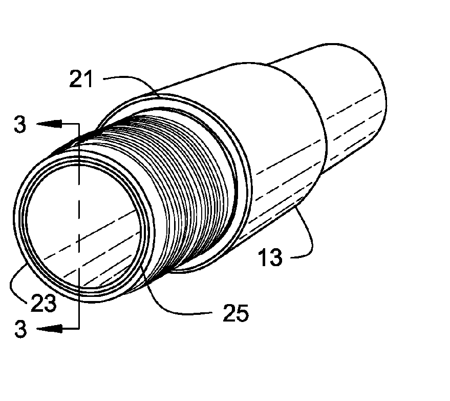
  • Downhole data transmission system
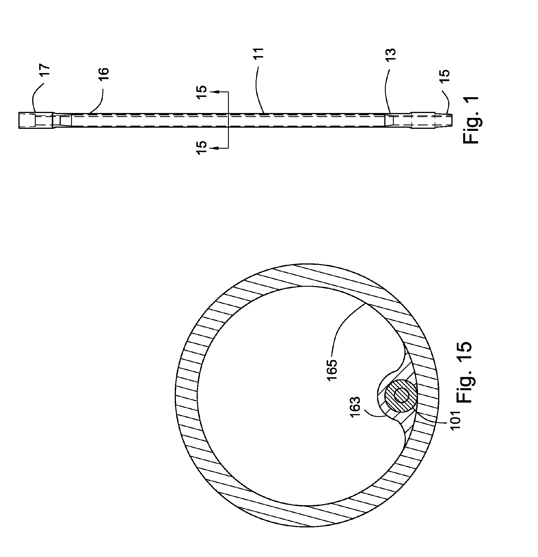
  • Downhole data transmission system
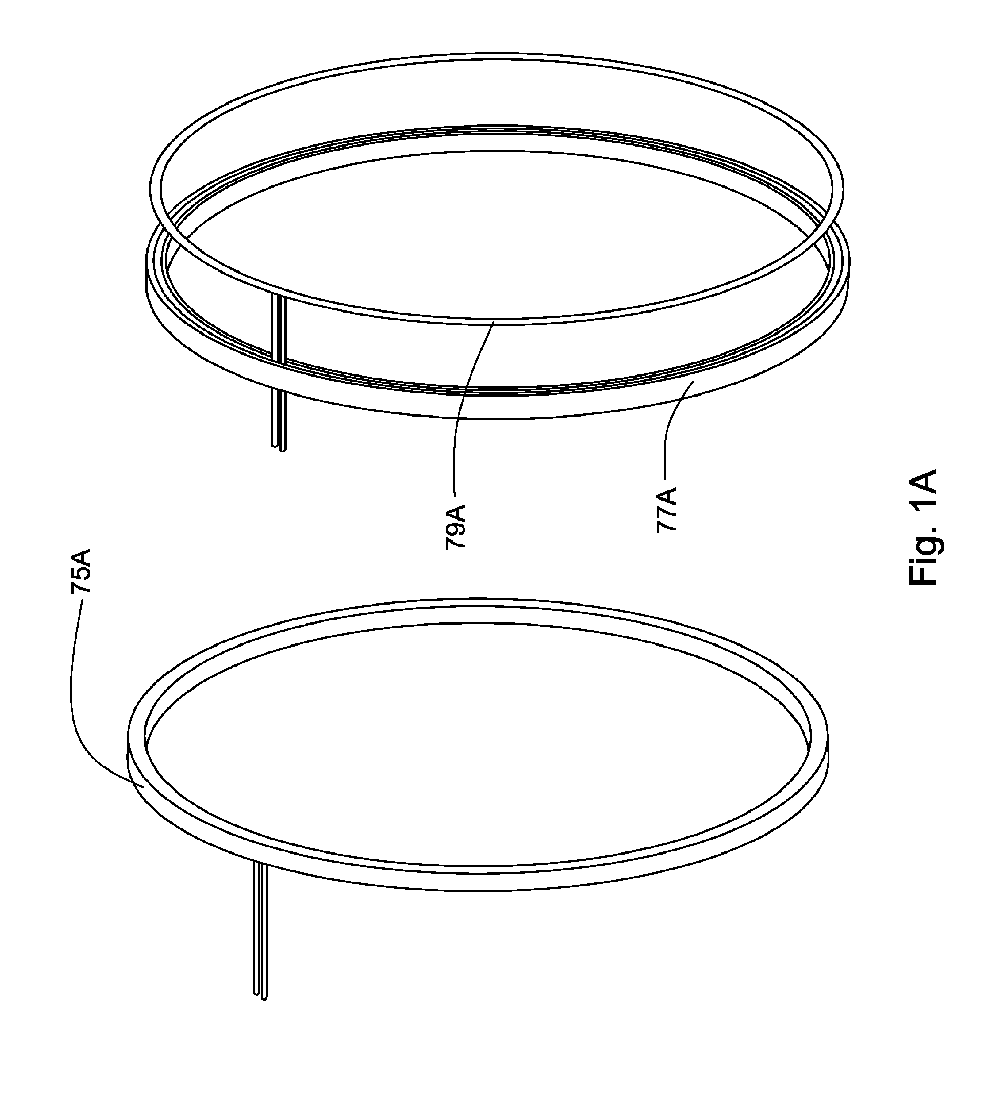
  • Downhole data transmission system

Examples

  • Experimental program(1)

Example

[0118] The following examples are provided by way of illustration and explanation and as such are not to be viewed as limiting the scope of the present invention.
[0119] Bench Test. Bench tests simulating connected pipe joints were conducted. The tests incorporated 30 sets of inductively coupled joints incorporating flexible segmented ferrite MCEI units in steel rings with recesses machined therein, each set being joined together in series by 34 feet of coaxial cable. The coupler consisted of 0.25-inch long by 0.100-inch diameter ferrite cylinders of permeability 125, having an inside diameter of about 0.05 inches, which were ground in half parallel to the cylindrical axis after infiltration with epoxy, bonding to a nylon chord substrate, and bonding into the groove in the steel. This simulated joint was used to characterize system transmission. A 2-volt peak-to-peak sinusoidal signal from a single 50-ohm, 2.5-mW power source energized the coupler of the first joint and produced a 22 mV, signal at last joint, into a 50 ohm load. Peak signal transmission was at 4.3 MHz, with a band width, at half height, of 2 MHz. The average attenuation in each pipe segment .backslash.was about 1.2 dB, corresponding to about 76% power transmission. About 70% of the attenuation was in the coaxial cable, which had a relatively small shield diameter (0.047 inches). The carrier signal was modulated with both analog and digital signals, demonstrating that that a recoverable, low power, high frequency, 56 kilobaud signal is achievable across 1000 feet of interconnected drill pipe without the aid of an additional power boost or signal restoration.
[0120] Drilling test. XT57 tool joints, one a pin end and the other a box-end, were obtained from Grant Prideco, Houston, Tex. The joints had an outside diameter of approximately 7" and an inside diameter of 4.750 inches, and they were adapted to receive the coupling transducer by machining an annular groove measuring 0.125".times.0.200" deep, having a full radius bottom surface of 0.060", approximately in the center of the 0.500" wide external and internal secondary shoulders, respectively, of the pin and box ends. A 0.500" internal shoulder was also machined into the pin-end joint approximately 9 inches from the end opposite its secondary shoulder. The machining increased a portion of the internal diameter of the pin end to about 5.250". A 0.375 inches borehole was gun drilled through the sidewalls of the two joints, parallel to their longitudinal axis. In the pin end, the borehole commenced within the groove and exited the internal shoulder. In the box end, the borehole commenced within the groove and exited the opposite end of the joint. The two joints were welded together, simulating a full-length pipe that normally would be more than 30 feet long. The change in the internal diameter of the welded joints allowed for positioning 30 feet of coaxial cable within the joint so that the test would electrically equivalent to a fulllength section of pipe.
[0121] The coupling transducer, having a nominal diameter of 4.700", comprising a grade 61 ferrite, with a permeability of about 125, obtained from Fair-Rite, was disposed within the annular grooves. The core of the coupler consisted of a segmented annular ferrite ring measuring approximately 0.100" wide by 0.050" high having a 0.050-inch diameter groove centrally located on its exposed face. The ferrite segments were attached to a substrate consisting of an epoxy impregnated nylon cord that served as a backing for the ferrite during the manufacturing process. A coil having two loops of 22-gauge (0.025 inch diameter), enamel coated copper magnet wire, was wound within the ferrite groove and held in place with aircraft epoxy. The wire and ferrite assembly were affixed within the grooves in the steel using a thermally cured polyurethane resin. The ends of the copper wire were allowed to extend approximately 0.5 inches beyond the coupler apparatus and were soldered to the conductors of a type 1674A, coaxial cable, 34 feet long, having a characteristic impedance 50 ohms, obtained from Beldon Cable. The cable was protectively sheathed within a thermoplastic PEEK.RTM. material obtained from Zeus Products, and the length of cable was coiled within the hollow portion of the joint assembly and held in place with a polyvinyl chloride (PVC) sleeve.
[0122] A drilling test was conducted in a 100 foot well using thirty physically short, electronically full-length joints configured as described above. A seven-inch roller-cone bit sub from Reed Tool was fitted with an accelerometer, an FM modulator, and a battery power supply, which were sealed in an annular insert housed within the crossover sub connecting the drill string with the bit. The joints were assembled so that their respective transducers were concentrically aligned to within approximately 0.010" of each other. In the test the drill bit drilled a cement plug with and without the aid of a drilling fluid. A 6V peak-to-peak sinusoidal signal (90 mW into 50 ohm) at the bit sub gave a clean 80 mV PP signal (50 ohm load) at the surface, which was 32 inductive couples and approximately 1000 electrical feet above the source signal. The two extra inductive pairs comprised a pair at the accelerometer sub and a rotary pair at the top drive. The audible portion of the accelerometer signal (below 20 kHz) produced an audio signal that enabled the ear to discriminate mud turbulence from drilling activity.

PUM

no PUM

Description & Claims & Application Information

We can also present the details of the Description, Claims and Application information to help users get a comprehensive understanding of the technical details of the patent, such as background art, summary of invention, brief description of drawings, description of embodiments, and other original content. On the other hand, users can also determine the specific scope of protection of the technology through the list of claims; as well as understand the changes in the life cycle of the technology with the presentation of the patent timeline. Login to view more.

Similar technology patents

Classification and recommendation of technical efficacy words

Why Eureka
Try Eureka