Differential oscillator

a differential oscillator and oscillator technology, applied in the direction of oscillator generators, pulse generation by logic circuits, pulse techniques, etc., can solve the problems of increasing oscillation period variations, reducing phase stability, and reducing the load of colpitt oscillators, so as to achieve high symmetry and improve phase stability.

Inactive Publication Date: 2004-06-17
TELEFON AB LM ERICSSON (PUBL)
View PDF3 Cites 18 Cited by
  • Summary
  • Abstract
  • Description
  • Claims
  • Application Information

AI Technical Summary

Benefits of technology

0015] It is also an object of the invention to provide a highly symmetric os

Problems solved by technology

Single-sided (non-differential) resonator based clock oscillators often suffer from poor noise rejection, which in turn reduces the phase stability and increases the oscillation period variations.
However, although the cl

Method used


Image

  • Differential oscillator
  • Differential oscillator
  • Differential oscillator

Examples


first embodiment

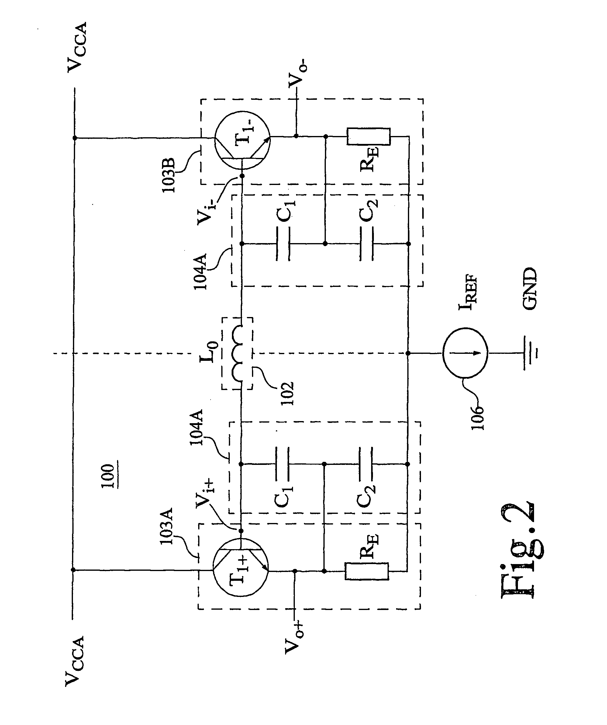
[0055] For a better understanding of the invention, the proposed oscillator architecture will now be described in detail with reference to the invention, as outlined in FIG. 2.

[0056] FIG. 2 is a schematic circuit diagram of a resonator-based differential oscillator, excluding tuning and bias circuitry, according to a first embodiment of the invention. The differential oscillator 100 basically comprises two branches interconnected by a common inductive element L.sub.0. Each branch includes an oscillator amplifier 103A / 103B with a capacitive local feedback path 104A / 104B. In this particular is example, each of the oscillator amplifiers 103A / 103B is preferably realized as a low-impedance buffer amplifier such as a transistor-based emitter follower. An emitter follower is basically a bipolar transistor T.sub.1+ / T.sub.1- in appropriate configuration with a resistance R.sub.E. It normally has a voltage gain that is slightly less than unity, a large current gain, large input impedance and ...

second embodiment

[0064] FIG. 4 is a schematic circuit diagram of a more elaborated differential oscillator according to the invention. In similarity to the differential oscillator of FIG. 2, each branch of the oscillator 200 includes an emitter follower buffer amplifier 203A / 203B with a capacitive local feedback path 204A / 204B. However, the differential oscillator shown in FIG. 4 also includes additional circuitry for various functions such as tuning and bias, amplifier gain limitation, crystal or SAW resonator enhancement as well as a voltage-reference-stabilized current source and first-level output buffers.

[0065] Instead of a single inductive element in the common connection link between the inputs of the emitter-follower based amplifiers 203A and 203B, the common link 202 now includes a crystal XTAL connected in series with the inductive element L.sub.0. It is also possible to use a surface acoustic wave (SAW) device for resonator enhancement instead of or in combination with the crystal. In thi...

third embodiment

[0071] FIG. 7 is a circuit diagram of a differential oscillator according to the invention. The differential oscillator 500 comprises two branches interconnected by a common capacitive link 502. In this realization, each of the local feedback paths associated with the emitter-follower based oscillator amplifiers 503A and 503B is made up of an inverting feedback amplifier 505A / 505B with an embedded capacitive phase shift filter. Preferably, the phase shift function in the feedback loop is generally based on an ideal inverting feedback amplifier together with the phase shift filter capacitor C.sub.1. In addition, by introducing an emitter-decoupling capacitor C.sub.E1 for each emitter-follower based oscillator amplifier 503A / 503B, the oscillator amplifier will also act as an integrator in the local feedback path. In practice, the emitter-decoupling capacitor C.sub.E1 forms an additional capacitive phase shifting element in the local feedback path. The resistance R.sub.C2 has a biasing...


PUM


Abstract

The invention relates to a new family of differential oscillators based on oscillator amplifiers with local feedback forming respective local feedback systems, and at least one common link interconnecting the local feedback systems. Each branch of the differential oscillator includes an oscillator amplifier with a phase shifting and impedance transforming local feedback path from the output to the input of the amplifier to form a local feedback system. The differential oscillator also includes one or more common phase shifting links for interconnecting and cooperating with the local feedback systems to enable self-sustained differential oscillation. In differential mode operation, the electrical midpoint of the common phase shifting link(s) is virtually grounded and the local feedback systems of the two branches operate, together with the common phase shifting link(s), effectively in anti-phase with respect to each other as two separate oscillators.

Description

[0001] The present invention generally relates to the field of oscillator design, and more specifically to differential oscillators.[0002] BACKGROUND OF THE INVENTION[0003] Oscillators can be found in numerous fields of technology, and are widely used for example in computers, telecommunication equipment and other electronic systems. With the ever-increasing demand for faster and more effective electronic systems comes the need for more and more sophisticated oscillators. In particular, the ever-increasing data processing and transmission rates in modern electronic systems reduce the timing margins between correlated signals and events. In this respect, a major source of uncertainty is the cycle-to-cycle variation (commonly denoted as jitter) in the various clock signals that are used as tiling references in such a system. Therefore, clock oscillators of high stability and low phase noise are of outmost importance in synchronous high-speed electronic systems.[0004] Single-sided (non...

Claims


Application Information

Patent Timeline
IPC IPC(8): H03B5/12H03B5/24H03K3/282
CPCH03B5/24H03K3/2823H03B5/1243H03B5/1212H03B5/1231
Inventor FREDRIKSSON, JESPER
Owner TELEFON AB LM ERICSSON (PUBL)
Why Eureka
Try Eureka