Optical amplifier, passing-wavelength characteristic control method in optical amplifier, and optical transmission system

a technology of optical amplifier and characteristic control method, which is applied in the direction of multiplex communication, electromagnetic repeaters, instruments, etc., can solve the problems of unfavorable affecting the quality of optical signals, unfavorable influence of wavelength characteristic of erbium-doped fiber of the first stage, and unnecessary excitation (waste)

Inactive Publication Date: 2004-07-15
FUJITSU LTD
View PDF11 Cites 20 Cited by
  • Summary
  • Abstract
  • Description
  • Claims
  • Application Information

AI Technical Summary

Problems solved by technology

The main cause of loss lies in the scattering of an optical signal outside a fiber or absorption by impurities within a fiber.
However, in this AGC state, there are cases where excitation becomes unnecessary (waste).
If the number of relay stages (amplification stages) is increased, the gain profile is accumulated and unfavorably affects the qualities of optical signals.
In the case of a combination of optical filters and stimulated Raman scattering, when stimulated Raman scattering is employed as a second-stage amplifier, the wavelength characteristic of the erbium-doped fiber of the first stage has an unfavorable influence on the stimulated Raman scattering of the second stage.
More specifically, if the shape of the gain profile of the erbium-doped fiber changes according to the secondary operating point, an administrative operator cannot cause the gain obtained by the stimulated Raman scattering of the second stage to be active or tunable according to wavelengths.
However, in the case of using optical wavelength monitors, optical transmission systems have to transfer monitoring light with a specific wavelength at all the bands of an optical amplifier.
Besides, the monitoring light is unnecessary because it is used solely for the purpose of monitoring the gain-wavelength characteristic of the optical amplifier.
Moreover, the administrative operator must cause customers to purchase redundant equipment such as an optical spectrum analyzer for monitoring, etc.
Therefore, the initial introduction cost that is imposed on customers is increased.
This feedback control is accurate, but is susceptible to external disturbance when increasing or decreasing wavelength channels (channels allocated to light wavelengths).
This filter control method requires a considerable time until control becomes stable.
In general, if interrupting transfer is needed when networks are connected in mesh form, fault recovery operation is indispensable and that interruption transfer is also time-consuming.
Therefore, gain tuning that employs optical wavelength monitors is temporally difficult and is not practical control.
Furthermore, the above-described optical amplifiers, such as an erbium-doped fiber amplifier, Raman fiber amplifier, etc., are not efficient in operation and contain many redundant portions that increase both power consumption and equipment costs.
Erbium-doped fiber amplifiers, and excitation lasers for stimulated Raman scattering, consume great power.
Therefore, each device requires a means of radiating heat generated by great power.
This heat-radiating means increases the size and cost of the transmission system.
Particularly, the large size of Raman fiber amplifiers causes increased costs.

Method used


Image

  • Optical amplifier, passing-wavelength characteristic control method in optical amplifier, and optical transmission system
  • Optical amplifier, passing-wavelength characteristic control method in optical amplifier, and optical transmission system
  • Optical amplifier, passing-wavelength characteristic control method in optical amplifier, and optical transmission system

Examples


first embodiment

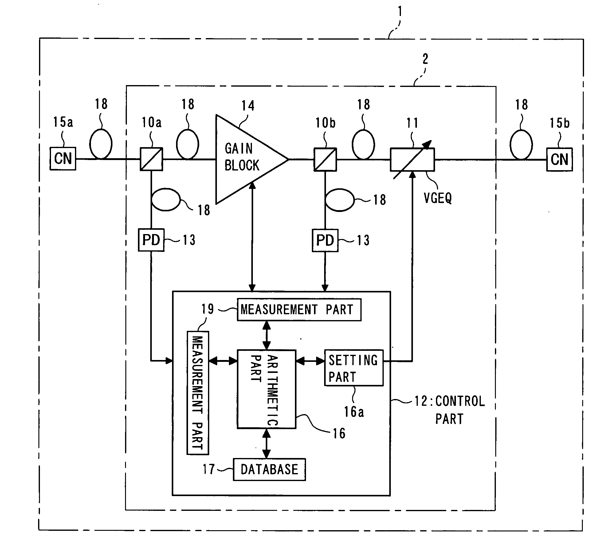
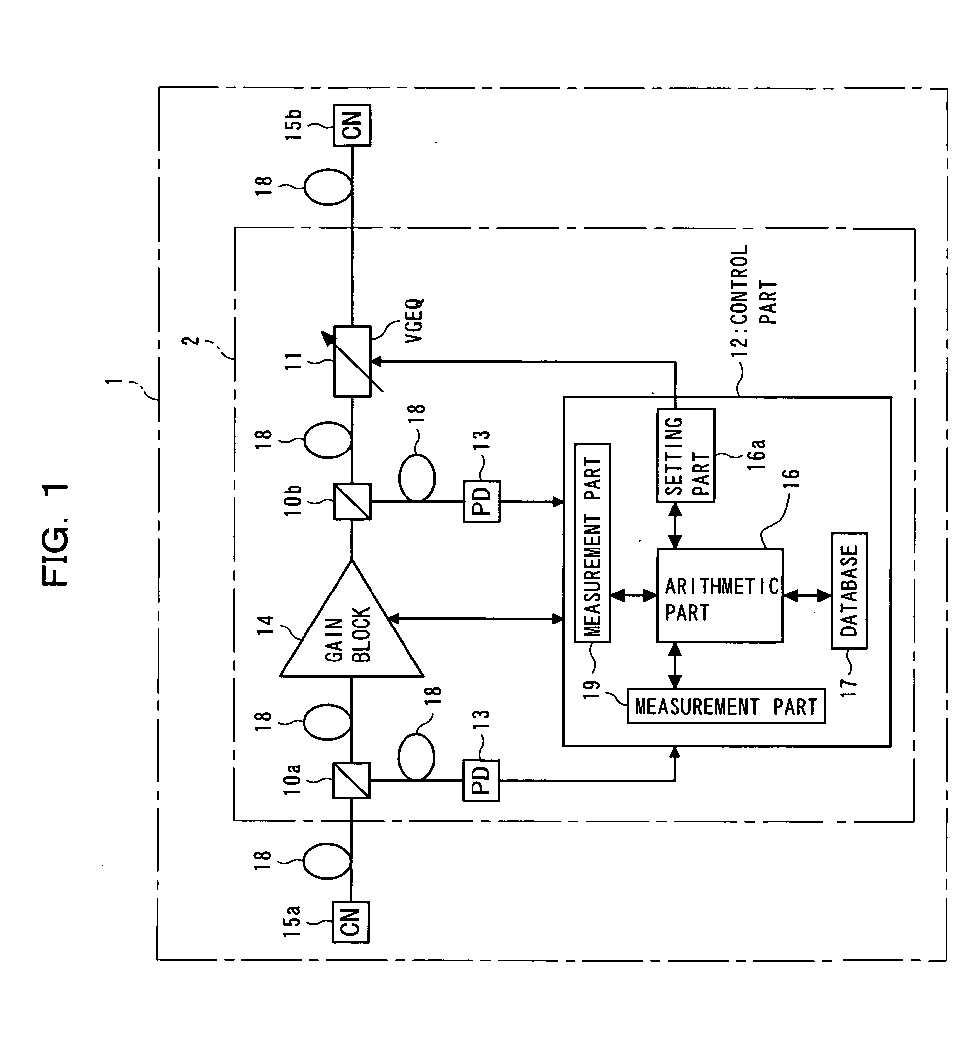
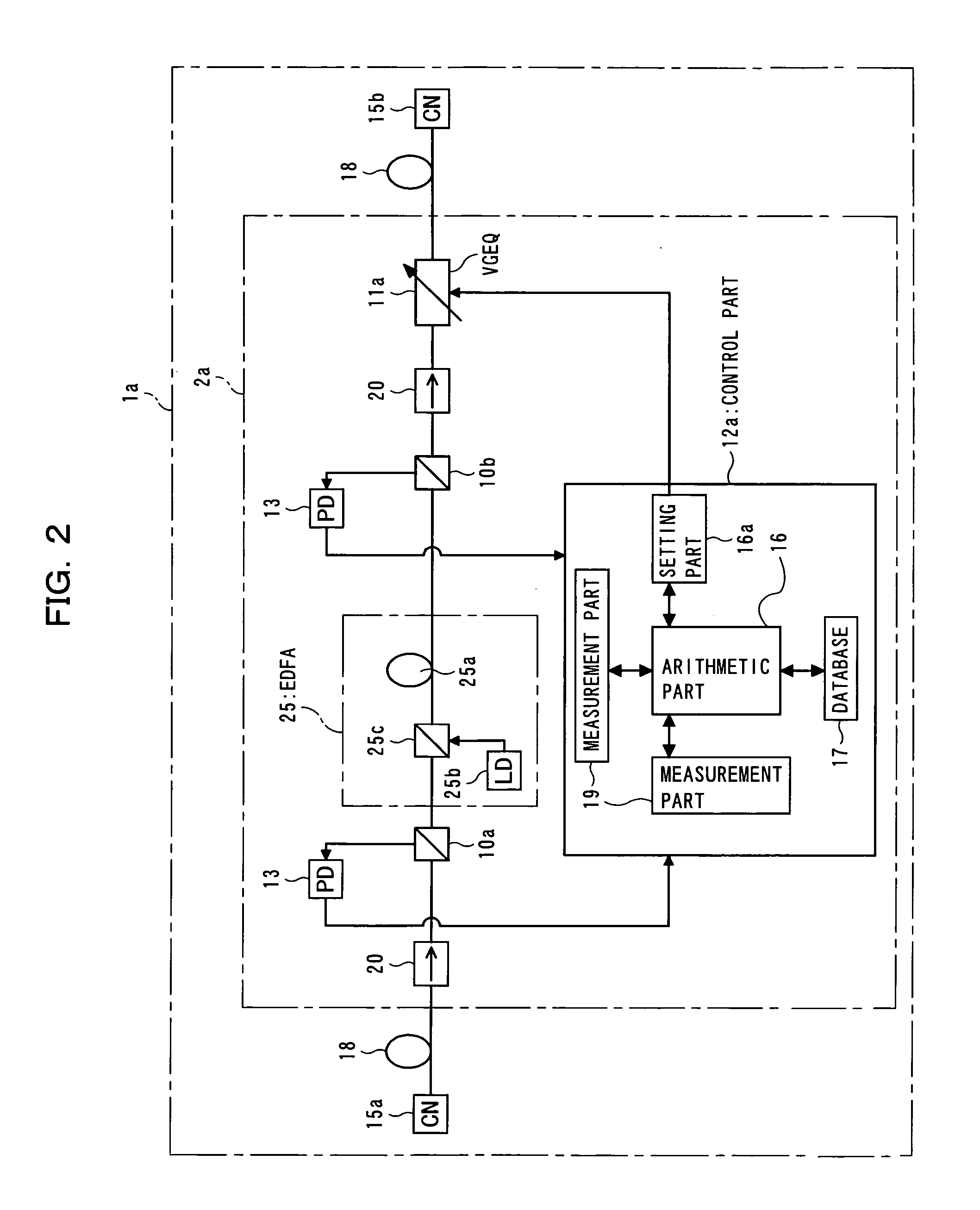
[0109] FIG. 2 shows an optical WDM transmission system constructed in accordance with the present invention. The optical transmission system 1a shown in the figure is used for transmitting WDM light and is provided with an optical amplifier 2a which is constructed of a centralized amplification type amplifier. The optical amplifier 2a is equipped with an erbium-doped fiber amplifier 25, optical isolators 20, and an optical filter 11a. The first optical isolator 20 is provided on the input side of the erbium-doped fiber amplifier 25 through a first optical coupler 10a, and the second optical isolator 20 is provided on the output side of the erbium-doped fiber amplifier 25 through a second optical coupler 10b. The optical filter 11a is provided on the output side of the optical isolator 20. The inverted passing-wavelength characteristic of the optical filter 11a is set by a control part 12a. In addition to these, parts with the same reference numerals as those described above have the...

second embodiment

[0134] (B) Description of the Second Embodiment

[0135] In a second embodiment of the present invention, a description will be given in the case where the gain block 14 (see FIG. 1) is constructed of a Raman fiber amplifier.

[0136] FIG. 8 is a diagram showing an optical WDM transmission system constructed in accordance with the second embodiment of the present invention. The optical transmission system 1b shown in the figure is used for transmitting WDM light and is equipped with a transmission line (Raman fiber amplifier) 18a having a Raman amplification function, and an optical amplifier 2b which outputs excitation light and monitors optical power. The control part 12b of the optical amplifier 2b computes the passing-wavelength characteristic of an optical filter 11a and sets the inverse of the computed passing-wavelength characteristic to the optical filter 11a. The control part 12b is equipped with a measurement part 19, a database 17, an arithmetic part 16, and a setting part 16a....

third embodiment

[0146] (C) Description of the Third Embodiment

[0147] A third embodiment is an alteration of the first and second embodiments. In the optical transmission system 1a or 1b with the optical amplifier 2a or 2b, the type and length of input-side transmission line 18 used are obtained from upstream supervisory (SV) light. This SV light contains information about the type of transmission line 18, transmission line length, etc. The SV light is an optical signal with a wavelength differing from wavelengths allocated to WDM light.

[0148] FIG. 9 shows an optical transmission system constructed in accordance with the third embodiment of the present invention. The optical transmission system 1c shown in the figure is equipped with optical WDM terminal stations (hereinafter referred to as terminal stations) 30, 31, again block 14, optical couplers J1 to J8 contained in an optical amplifier 2a (or 2b), and a coupler 32. Note that optical signals are transmitted in a first direction from the first t...


PUM

PropertyMeasurementUnit
wavelengthaaaaaaaaaa
input optical poweraaaaaaaaaa

Abstract

An optical amplifier, provided in a WDM transmission system, contains an amplification medium for amplifying WDM light, a measurement part for measuring at least one input optical power of the WDM light on both input and output sides of the amplification medium, a variable gain equalizer for variably setting a passing-wavelength characteristic, a database for holding data representing wavelength characteristics that respectively correspond to transmission line types, an arithmetic part for computing an inverted passing-wavelength characteristic resulting from a passing-wavelength, based on an acquired transmission line type, the optical power measured by the measurement part, and the data held in the database, and a setting part for setting a passing-wavelength characteristic of the variable gain equalizer, based on the inverted passing-wavelength characteristic computed by the arithmetic part, and with this, capable of controlling optical filters more quickly and amplifying optical signals more efficiently in WDM systems.

Description

[0001] (1) Field of the Invention[0002] The present invention relates to an optical amplifier suitable for controlling the passing-wavelength characteristic of amplified wavelength-division-multiplexed (WDM) light, and relates to a passing-wavelength characteristic control method in that optical amplifier, and an optical transmission system.[0003] (2) Description of the Related Art[0004] With a rapid increase in the number of Internet users and start of distribution service such as images, etc., there is an increasing strong demand for continuous access to high-speed optical networks that are the backbone of Internet. A wavelength-division multiplexing (WDM) system, which multiplexes and transmits a plurality of optical signals of different wavelengths through a single optical fiber (hereinafter referred to as a fiber), has been desired to be put to practical use, because it can increase its transmission capacity in proportion to the number of wavelengths.[0005] Optical networks wit...

Claims


Application Information

Patent Timeline
Patent Type & Authority Applications(United States)
IPC IPC(8): G02F1/35H01S3/10G02B5/18H04B10/079H04B10/29H04B10/294H04J14/00H04J14/02
CPCH04B10/2941H04B10/2916
Inventor SUGIYA, HIDEAKI
Owner FUJITSU LTD
Why Eureka
Try Eureka