
Apparatus and method for treatment of cerebral aneurysms, arterial-vascular malformations and arterial fistulas

a technology of aneurysms and aneurysms, applied in the field of apparatus and methods for treating cerebral aneurysms, arterialvascular malformations and arterial fistulas, can solve the problems of severe neurological complications, aneurysms that cannot hold wires or other emboli inside the cavity, and described methods that are not applicable to aneurysms that canno

Inactive Publication Date: 2004-08-12
CHORNENKY VICTOR I +1
View PDF18 Cites 21 Cited by
  • Summary
  • Abstract
  • Description
  • Claims
  • Application Information

AI Technical Summary

Benefits of technology

The method effectively stabilizes aneurysms by creating a resistant thrombus on the aneurysm's inner surface, reducing the risk of rupture and further growth, and can be applied to various shapes and types of aneurysms, including those without defined necks.

Problems solved by technology

If not treated, an aneurysm continues to grow until it ruptures, causing a subarachnoid hemorrhage (that is, bleeding between the middle membrane covering of the brain and the brain itself), severe neurological complications, and, possibly, death.
The described methods are not applicable to aneurysms that do not have obviously defined necks (narrow openings between the artery and the aneurysm sac).
Such aneurysms can't hold the wires or other emboli inside the cavity.
Another shortcoming of the described methods is that the blood clot, formed by blood stagnation inside the cavity or its heating, is relatively weak.
The fresh arterial blood, coming into the aneurysm can cause lysis (dissolution) of the clot inside the sac and create a chance that a piece of wire or a piece of clot can be displaced from the aneurysm into the blood stream and embolize distally.

Method used


Image

  • Apparatus and method for treatment of cerebral aneurysms, arterial-vascular malformations and arterial fistulas
  • Apparatus and method for treatment of cerebral aneurysms, arterial-vascular malformations and arterial fistulas
  • Apparatus and method for treatment of cerebral aneurysms, arterial-vascular malformations and arterial fistulas

Examples


Embodiment Construction

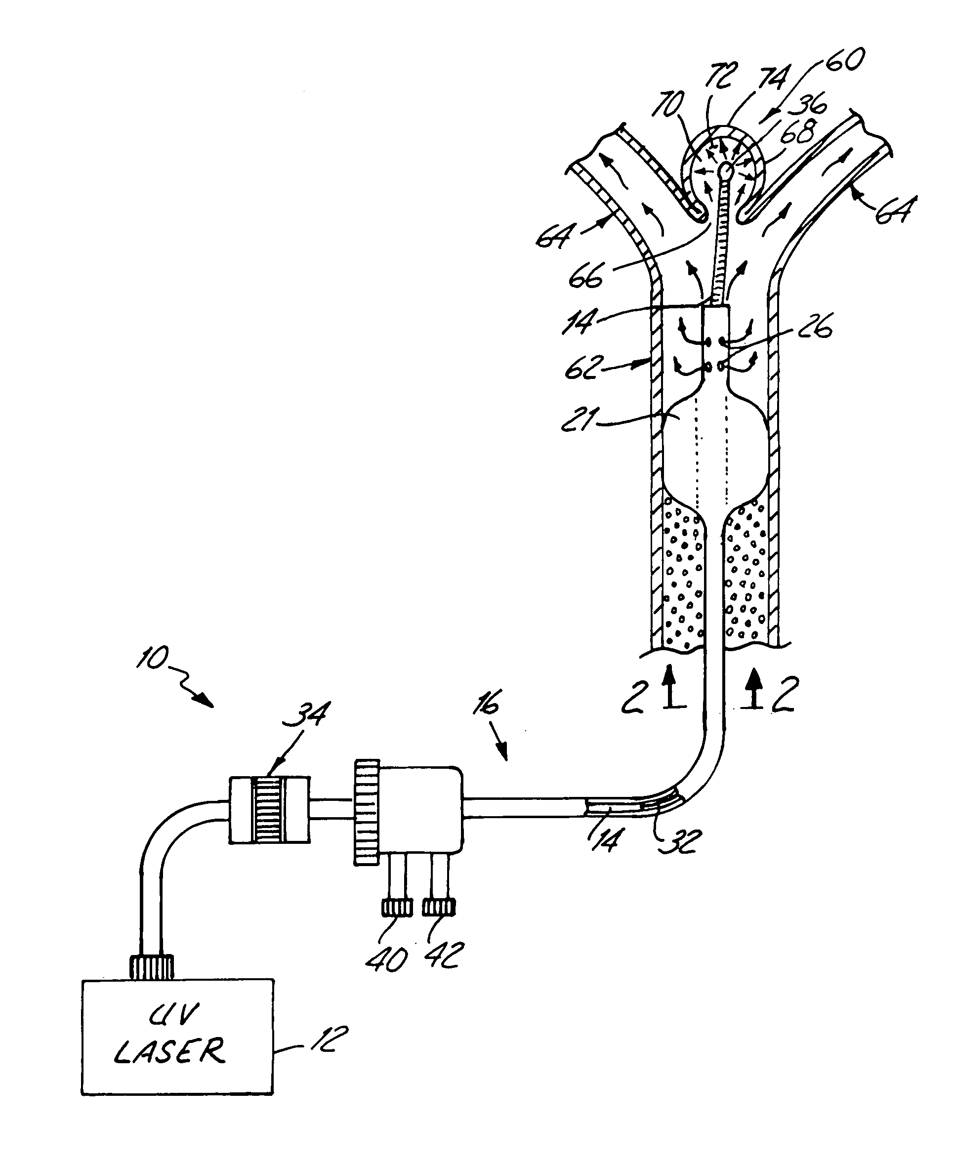
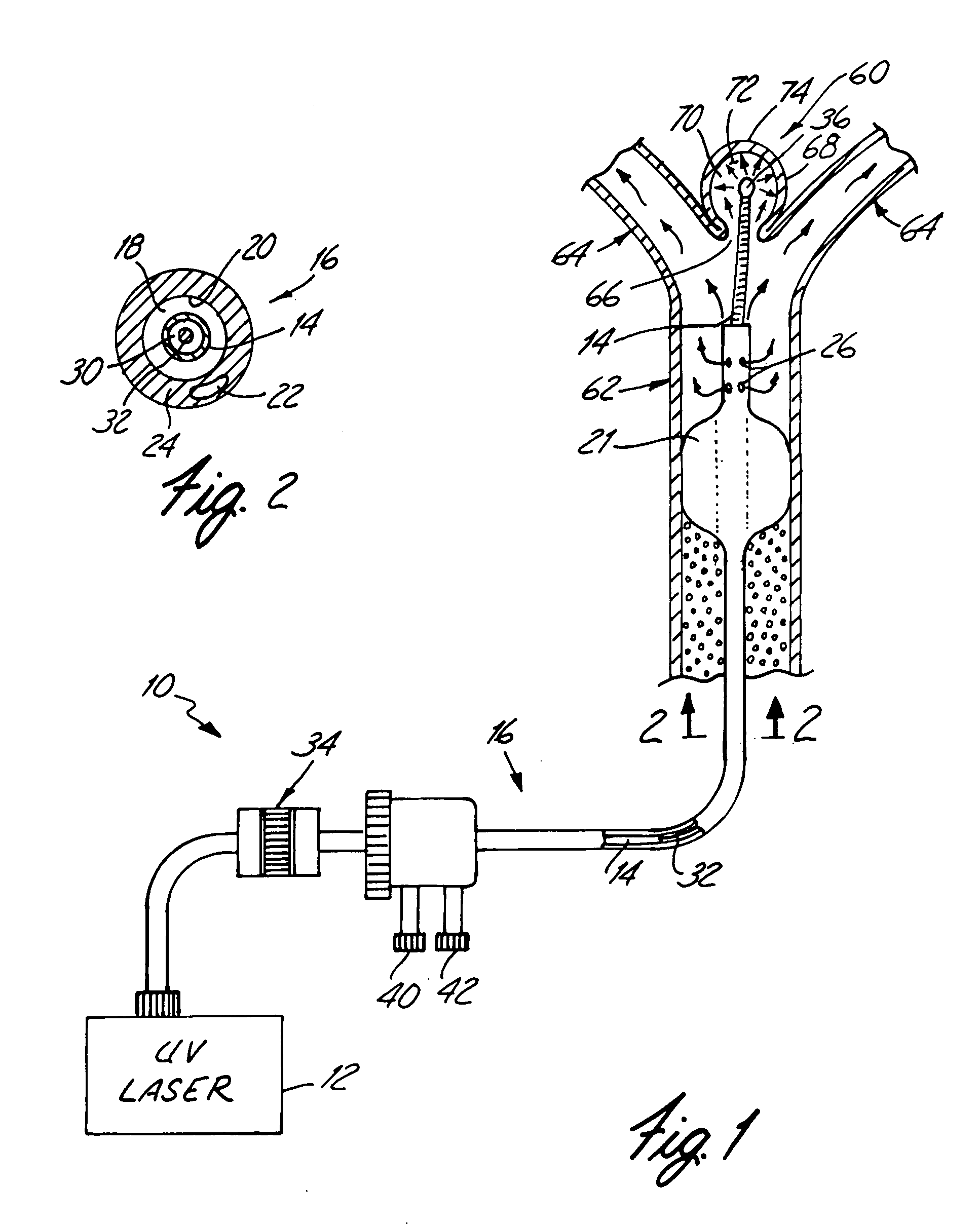
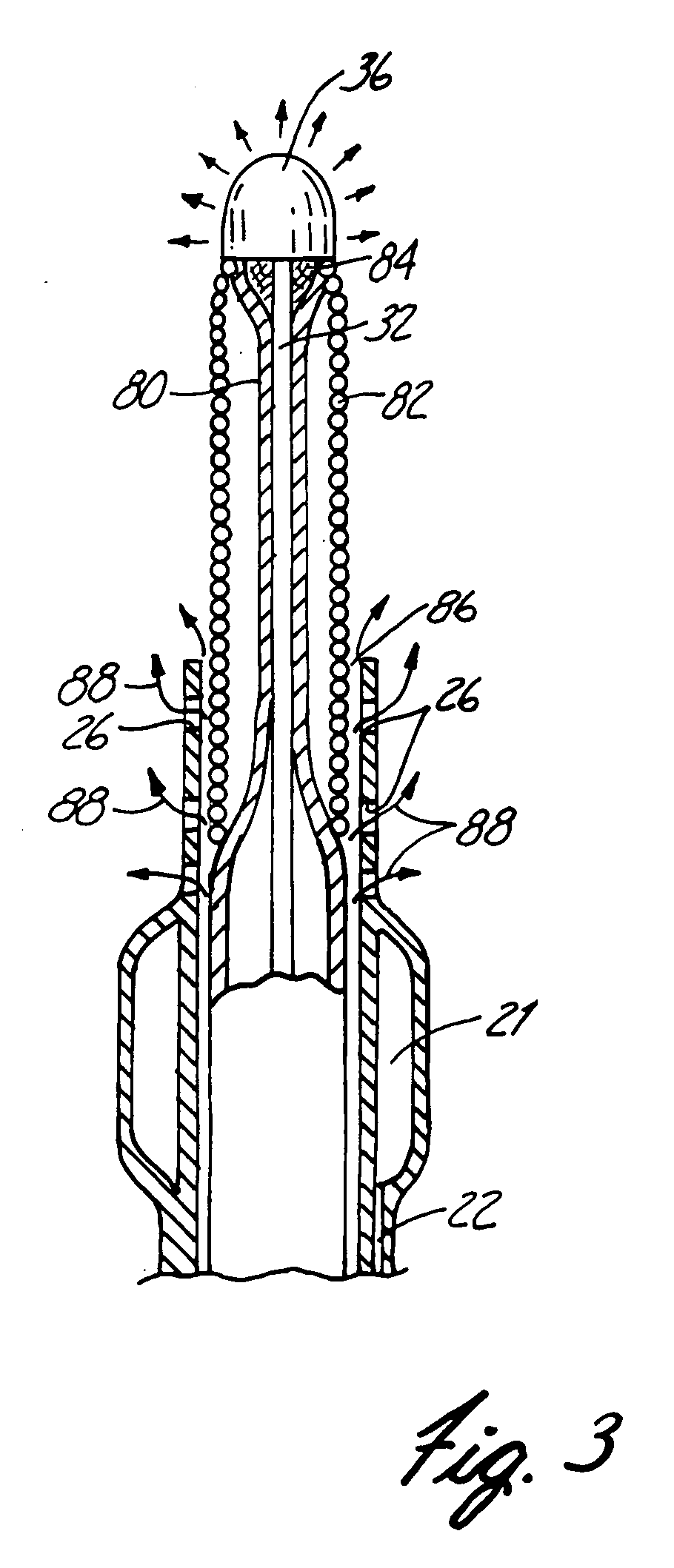
[0026] An apparatus 10 for treatment of an aneurysm and in accord with the present invention is schematically shown in FIGS. 1 and 2. Apparatus 10 comprises a laser 12, a steerable guide wire 14, and a catheter 16. Catheter 16 will be appropriately sized depending upon where in the patient's body a treatment will occur. For treatment of a cerebral aneurysm, which may require navigation through very small blood vessels in the brain, catheter 16 will be a microtube in the form of an elongated tube and may include a substantially centrally disposed tubular passage 18 defined by a wall 20 for receiving guide wire 14. Catheter 16 may, as shown in FIG. 1, also include an expandable balloon 21, which is used for occluding an artery during an interventional surgical procedure. Catheter 16 may also include a channel 22 disposed in the catheter wall 24 that is in fluid communication balloon 21.

[0027] Guide wire 14 has a tubular configuration and thus defines a tubular passage 30 receiving an ...


PUM


Abstract

An apparatus and method for stabilization of aneurysm is disclosed. The apparatus comprises an ultraviolet radiation generator for generating UV radiation having a wavelength, strongly absorbed by the DNA and a catheter including means for delivering the ultraviolet radiation to the aneurysm. The distal end of the catheter is placed inside the aneurysm. Stabilization of the aneurysm is achieved by forming a mural arterial thrombus inside the aneurysm. To make irradiation possible, the blood is displaced from the aneurysm by a steady stream of UV radiation transparent fluid. The injury to the endothelium that triggers the thrombus formation is caused by UV radiation delivered to the aneurysm. In several days after intervention the thrombus becomes fully organized, leaving on the inside surface of the aneurysm a thick layer of fibrotic tissue that stabilizes the aneurysm.

Description

[0001] The present invention relates generally to apparatus and methods for the treatment of vascular disease and particularly to apparatus and method for treatment of cerebral aneurysms, arterial vascular malformations and arterial fistulas using lasers.BACKGROUND INFORMATION[0002] Cerebrovascular disease is the third leading cause of death in the United States ranking behind only coronary artery disease and cancer. This disease can take several forms, including but not limited to cerebral aneurysm, arterial venous malformations (AVMs) and arterial fistulas (collectively referred to hereafter as "aneurysms.") One of the most important forms of this disease is the cerebral aneurysm, which manifest itself as a dilatation, or pouching of the arterial wall. As the disease progresses, the dilatation develops into a distended sac of thinned, stressed arterial tissue with a size of 5 to 10 mm in diameter. If not treated, an aneurysm continues to grow until it ruptures, causing a subarachn...

Claims


Application Information

Patent Timeline
Patent Type & Authority Applications(United States)
IPC IPC(8): A61B17/22A61B18/22A61B18/24A61N5/06A61N5/067
CPCA61B18/24A61B2017/22051A61N2005/067A61N5/0601A61N2005/0661A61B2018/2261A61N5/067
Inventor CHORNENKY, VICTOR I.JAAFAR, ALI
Owner CHORNENKY VICTOR I
Learn More