Dual gas facility

a gas facility and gas technology, applied in the direction of container discharging methods, container filling under pressure, transportation and packaging, etc., can solve the problems of affecting the efficiency of gas pumping, and stranded gas that is produced concurrently with crude oil, etc., to achieve the effect of reducing or eliminating icing, balancing friction losses, and less efficien

Inactive Publication Date: 2004-10-07
CONVERSION GAS IMPORTS
View PDF18 Cites 12 Cited by
  • Summary
  • Abstract
  • Description
  • Claims
  • Application Information

AI Technical Summary

Benefits of technology

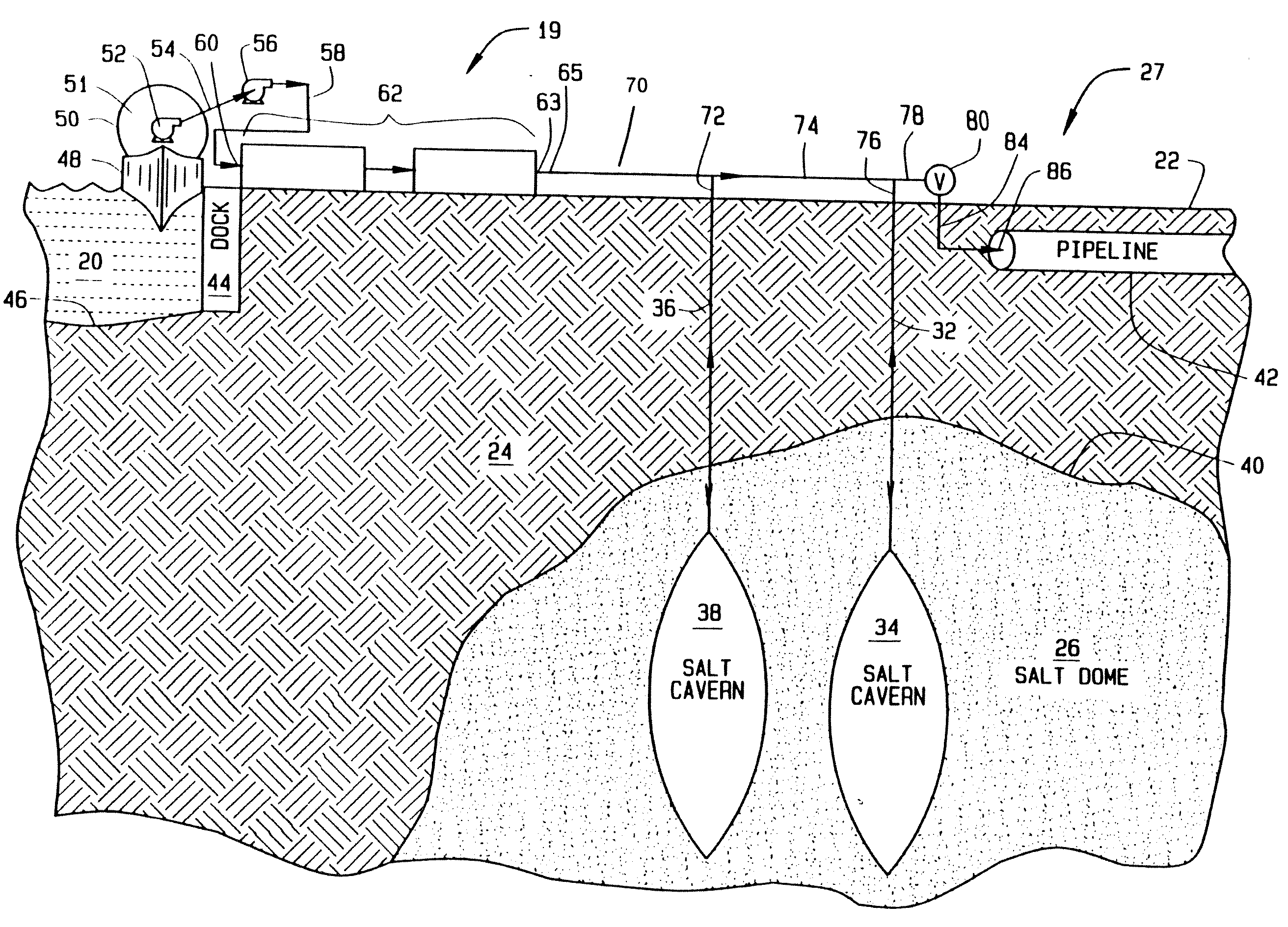
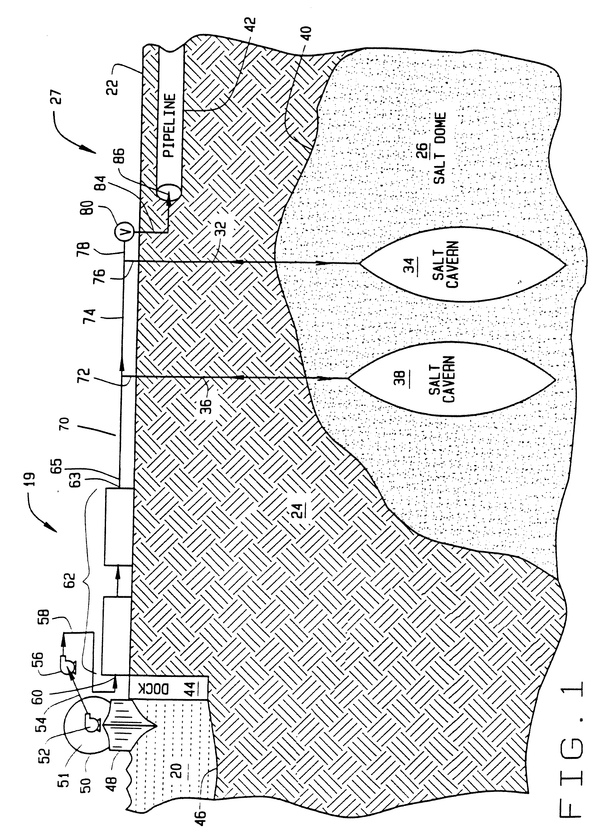
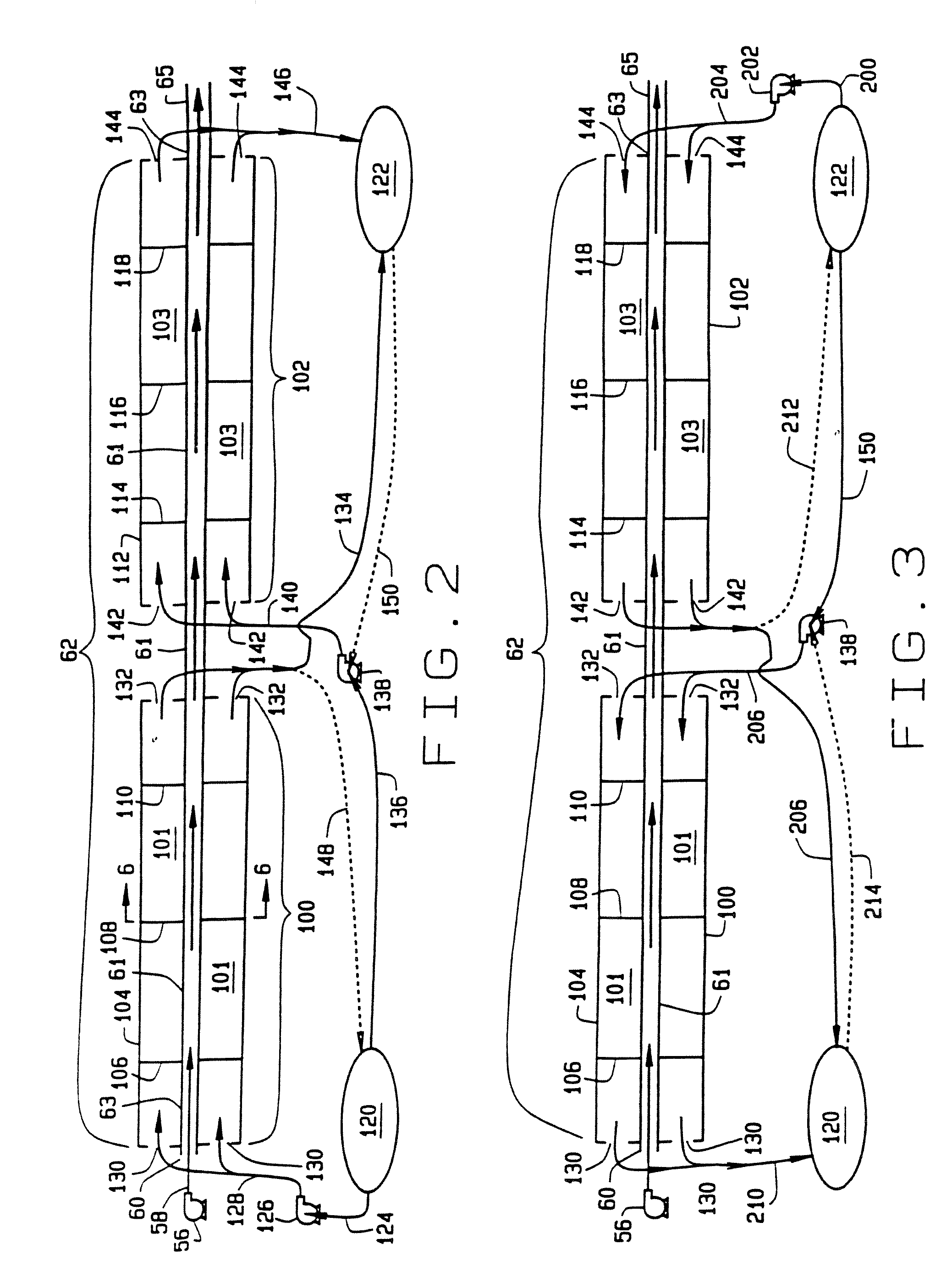
0053] It is important to avoid freez-up of the heat exchanger 62. Freez-up blocks the flow of warmant 94 and renders the heat exchanger 62 inoperable. It is also important to reduce or eliminate icing. Icing renders the heat exchanger 62 less efficient. It is therefore necessary to carefully design the area, generally identified by the numeral 63 where the cold fluid 51 in the pipe 61 first encounters the warmant 99 in the annular area 101 of the first section 100 of the heat exchanger 62. Here it is necessary to prevent or reduce freezing of the warmant 99 on the pipe 61, which could block the ports, 130 and the annular area 101. In most cases, it is possible to choose flow rates and pipe diameter ratio such that freezing is not a problem. For example, if a dense phase natural gas expands by a factor of four in the warming process, the heat balance then indicates that the warmant flow rate is required to be four times that of the inlet dense phase. This results in a diameter ratio of two (outer pipe / inner pipe) in order to balance friction losses in the two paths. However, the heat transfer rate is improved if the diameters are closer together. An optimum ratio is approximately 1.5. Where conditions are extreme, it is possible to prevent local freezing by increasing the thermal insulation at the wall of the cryogenically compatible pipe 61 in this region 63. One method for doing this is to simply increase the wall thickness of the pipe 61. This has the effect of pushing some of the warming function downstream to where the cold fluid 51 has already been warmed to some extent, and the possibility of freezing has been reduced. This may also increase the length of the heat exchanger.

Problems solved by technology

In other parts of the world, there is also natural gas production, but sometimes there is no pipeline network to transport the gas to market.
In the industry, this sort of natural gas is often referred to as "stranded" because there is no ready market or pipeline connection.
As a result, this stranded gas that is produced concurrently with crude oil is often burned at a flare.
It typically may take 12 hours or more to pump the LNG from the ship to the cryogenic storage tanks onshore.
LNG transport ships may cost more than $100,000,000 to build.
These tanks are not available to receive LNG from another ship until they are again mostly emptied.
Unfortunately, some of the gas is used as a heat source in the vaporization process, or if ambient temperature fluids are used, very large heat exchangers are required.
LNG cryogenic storage tanks are expensive to build and maintain.
Further, the cryogenic tanks are on the surface and present a tempting terrorist target.
Some, but not all of these salt formations are suitable for cavern storage of hydrocarbons.
If a cryogenic fluid at sub-zero temperature is pumped into a cavern, thermal fracturing of the salt may occur and degrade the integrity of the salt cavern.
For this reason, LNG at very low temperatures cannot be stored in conventional salt caverns.
The '905 patent does not disclose use of an uncompensated salt cavern.
Furthermore, there are limitations on the injection and send out capacity of depleted and partially depleted gas reservoirs that are not present in salt cavern storage.
In addition, temperature variances between the depleted reservoir and the injected gas create problems in the depleted reservoir itself that are not present in salt cavern storage.
In periods of high natural gas demand salt cavern storage facilities are depleted rapidly and generally the storage inventories are not replenished until periods of low natural gas demand.
In periods of continued high demand for natural gas such as in a prolonged cold wave there may be an inability to refill the salt cavern storage facility because of the general inability of the U.S. domestic production of natural gas to match the high rates of natural gas consumption.

Method used


Image

  • Dual gas facility
  • Dual gas facility
  • Dual gas facility

Examples


example # 2

[0077] This hypothetical example is designed to give broad operational parameters for the Bishop One-Step Process conducted offshore as shown in FIGS. 4 and 5. A number of factors must be considered when designing the facilities 298 and 299 including the type of cold fluid and the temperature of the warmant that will be used. Conventional instrumentation for process measurement, control and safety are included in the facility as needed including but not limited to: temperature and pressure sensors, flow measurement sensors, overpressure reliefs, regulators and valves. Various input parameters must also be considered including, pipe geometry and length, flow rates, temperatures and specific heat for both the cold fluid and the warmant. Various output parameters must also be considered including the type, size, temperature and pressure of the uncompensated salt cavern. For delivery directly to a pipeline, other output parameters must also be considered such as pipe geometry, pressure,...

example # 3

[0105] This hypothetical example is merely designed to give broad operational parameters for an alternative embodiment including a vaporizer system for warming of cold fluids with subsequent storage in uncompensated salt caverns and / or transportation through a pipeline, as shown in FIG. 10. Unlike conventional LNG facilities, no cryogenic tanks are used in the on-shore facility 310 of FIG. 10. (The ship 48, as previously mentioned, does contain cryogenic tanks 50.) A conventionally designed vaporizer system 260 is used in this alternative embodiment instead of the coaxial heat exchangers 62 and 220, discussed in the previous examples. (Conventional vaporizer systems typically operate in the range of 1,000-1,200 psig.) The conventionally designed vaporizer system 260 will need to be modified to accept the higher pressures associated with uncompensated salt caverns (typically in the range of 1,500-2,500 psig). A number of factors must be considered when designing the facility 310 incl...

example # 4

EXAMPLE #4

[0119] This hypothetical example is designed to give broad operational parameters for the Flexible Natural Gas Storage Facility 400 as shown in FIG. 11.

[0120] When the LNG source for the Flexible Natural Gas Storage Facility 400 is a cold fluid transport ship 48 offloading at a dock with a land based Bishop Process.TM. Heat Exchanger, then previous Example 1 is relevant. When the LNG source for the Flexible Natural Gas Storage Facility 400 is a cold fluid transport ship 48 moored to an offshore facility with an offshore Bishop Process.TM. Heat Exchanger, then previous Example 2 is relevant. In a typical situation, the high pressure LNG pump raises the pressure of the LNG to cavern pressure. The Bishop Process.TM. Heat Exchanger then warms the fluid to a temperature that is compatible with the salt cavern, typically about 40.degree. F. The optional booster compressor may be necessary to replace pressure lost due to pipeline friction or pressure drops due to distance or pipe...


PUM


Abstract

The Dual Gas Facility stores natural gas in one or more man-made salt caverns typically located in a single salt dome or in bedded salt. The Dual Gas Facility can access different sources of natural gas. A first gas source is from a natural gas pipeline(s) and a second gas source is from LNG. Depending on economic conditions, supply conditions and other factors, the Dual Gas Facility can receive gas from the natural gas pipeline(s) and/or from LNG to fill the salt caverns. Of course, the LNG must be warmed before being stored in a salt cavern.

Description

[0001] This application is a continuation of U.S. application Ser. No. 10 / 384,156 filed on Mar. 7, 2003, which is a continuation-in-part of application Ser. No. 10 / 246,954 filed on Sep. 18, 2002 which claims priority of U.S. provisional patent application 60 / 342,157 filed Dec. 19, 2001.BACKGROUND OF INVENTION[0002] Much of the natural gas used in the United States is produced along the Gulf Coast. There is an extensive pipeline network both offshore and onshore that transports this natural gas from the wellhead to market. In other parts of the world, there is also natural gas production, but sometimes there is no pipeline network to transport the gas to market. In the industry, this sort of natural gas is often referred to as "stranded" because there is no ready market or pipeline connection. As a result, this stranded gas that is produced concurrently with crude oil is often burned at a flare. This is sometimes referred to as being "flared off."[0003] Different business concepts ha...

Claims


Application Information

Patent Timeline
Patent Type & Authority Applications(United States)
IPC IPC(8): F17C3/00F17C5/06F17C7/00F17C9/02
CPCF17C3/005F17C5/06F17C7/00F17C9/02F17C2205/0364F17C2221/033F17C2223/0115F17C2223/0123F17C2223/0161F17C2223/033F17C2225/0115F17C2225/0123F17C2225/035F17C2225/036F17C2227/0135F17C2227/0157F17C2227/0185F17C2227/0309F17C2227/0316F17C2227/0318F17C2227/0323F17C2227/033F17C2227/0337F17C2227/0388F17C2227/0393F17C2227/0395F17C2250/0456F17C2265/05F17C2265/068F17C2270/0105F17C2270/0152
Inventor BISHOP, WILLIAM M.MCCALL, MICHAEL M.
Owner CONVERSION GAS IMPORTS
Why Eureka
Try Eureka