On the other hand, transmission characteristics deteriorate when non-linear effects occur in optical fibers.
However, in the above-mentioned dispersion-compensating optical fibers of the prior art, although such optical fibers have been developed which attempt to improve the so-called
performance index (FOM;
Figure of Merit), which indicates the amount of chromatic dispersion per unit loss, while also being able to compensate the dispersion slope, it has been difficult to simultaneously realize these characteristics along with enlargement of Aeff.
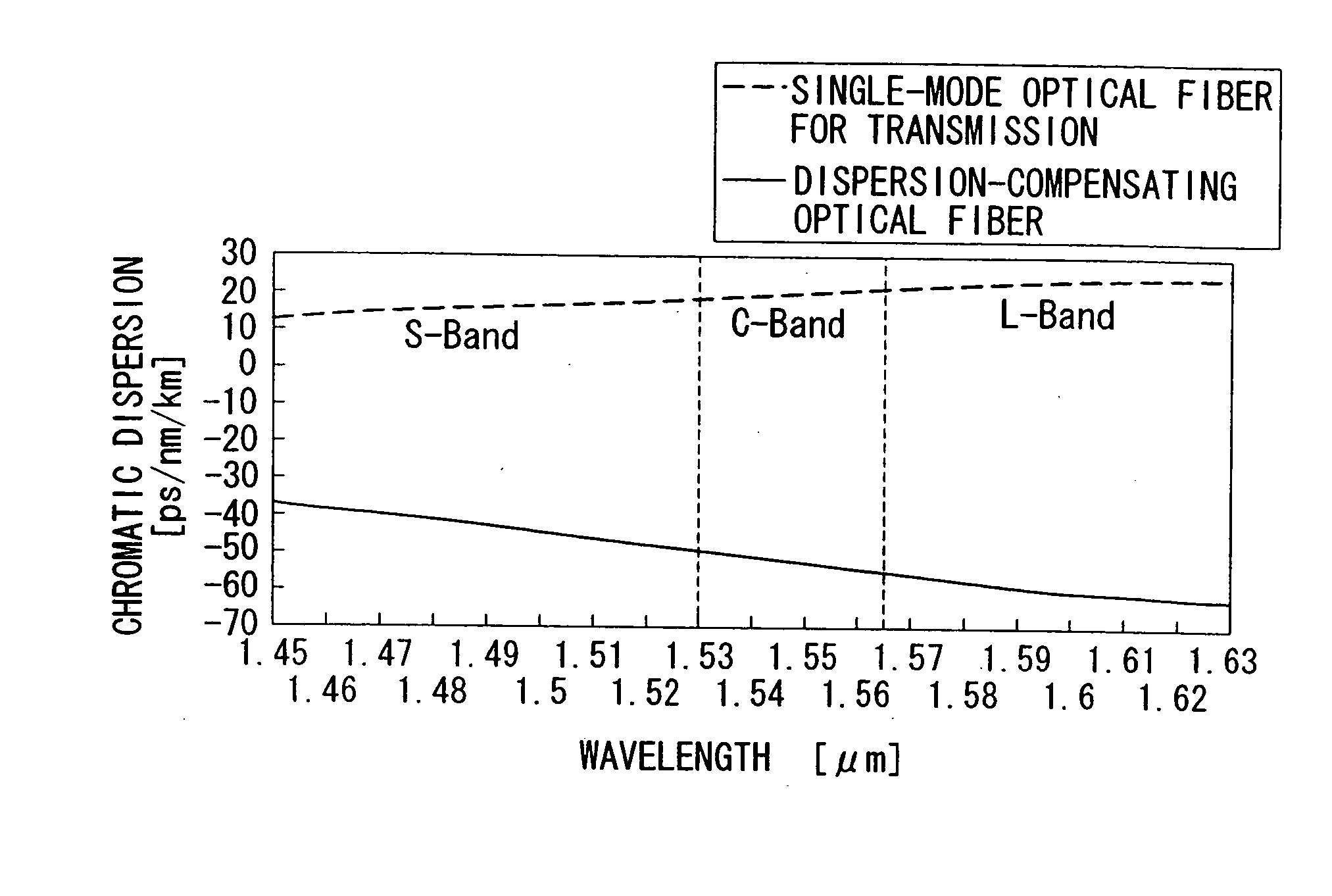
Thus, although a dispersion-compensating optical fiber is required that is able to compensate the chromatic dispersion and dispersion slope of single-mode optical fibers for transmission in not only the C-band, but also other wavelength bands such as the S-band and L-band, conventional dispersion-compensating optical fibers have been unable to adequately satisfy this requirement.
Consequently, these optical fibers have been inadequate particularly in applications to wavelength
multiplexing, high-speed, long-distance transmission and so forth.
In addition, although large Aeff is also simultaneously required in these wavelength bands, conventional dispersion-compensating optical fibers were unable to accommodate this requirement as well.
However, although reports have been made regarding dispersion-compensating optical fibers of the dispersion slope-compensating type that place the emphasis on compensation of chromatic dispersion and dispersion slope as well as reduction of loss, there have been no effective studies or reports made regarding enlargement of Aeff.
In addition, dispersion-compensating optical fibers of the prior art required that, for example, the
refractive index of the core center be larger than that of an ordinary single-mode optical fiber, and had the problem of increasing the amount of
dopant doped to the core center.
Thus, if the amount of
dopant doped increases, since the difference in viscosities of the core and cladding increases when the fiber base material is heated and melted to draw the optical fiber, the drawing rate and drawing temperature are restricted from the viewpoint of
mechanical strength, thereby resulting in the problem of being unable to obtain a dispersion-compensating optical fiber with low loss.
In addition, if the
refractive index of the core center is high, Aeff tends to decrease.
This results in greater susceptibility to the occurrence of non-linear effects, thereby leading to the problem of deterioration of transmission characteristics.
However, in the dispersion-compensating optical fibers of the prior art, optical fibers realizing chromatic dispersion and dispersion slope compensating effects while enabling the
refractive index of the core center to be comparatively small have been unable to be obtained, resulting in problems in terms of ease of production, low loss and non-
linearity, etc.
In addition, if Aeff is enlarged in an example of a dispersion-compensating optical fiber of the prior art, the absolute value of chromatic dispersion tends to become smaller, resulting in the problem of the length for compensating single-mode optical fibers for transmission becoming excessively long.
In the case the chromatic dispersion is larger than -50 ps / nm / km and approaches zero, there are disadvantages such as the used length of the dispersion-compensating optical fiber becoming long during compensation of a 1.3 .mu.m single-mode optical fiber over the entire
wavelength range of 1.53-1.63 .mu.m.
Furthermore, in a dispersion-compensating optical fiber of the prior art, even if a dispersion-compensating optical fiber is attempted to be designed to match the conditions of 1.3 .mu.m single-mode optical fibers in this manner, satisfactory characteristics were unable to be obtained particularly in the L-band.
If the used length is less than 1 / 6, there are cases in which chromatic dispersion is unable to be adequately compensated, and if the used length exceeds 1 / 3, there are cases in which transmission characteristics deteriorate.
It goes without saying, however, that such characteristic values cannot be obtained with dispersion-compensating optical fibers known in the prior art.
If Aeff is less than 30 .mu.m.sup.2, suppressedly effects on non-
linearity effects diminish, thereby making this disadvantageous.
If bending loss exceeds 40 dB / m, loss increases due to the slightest bending applied when laying the optical fiber, thereby making this disadvantageous.
If chromatic dispersion is greater than -10 ps / nm / km and approaches zero, it becomes difficult to compensate the chromatic dispersion of a single-mode optical fiber for transmission.
In the case of that in which chromatic dispersion is less than -40 ps / nm / km, Aeff ends up becoming small, substantially making production difficult.
Furthermore, it goes without saying, however, that such characteristic values cannot be obtained with dispersion-compensating optical fibers known in the prior art.
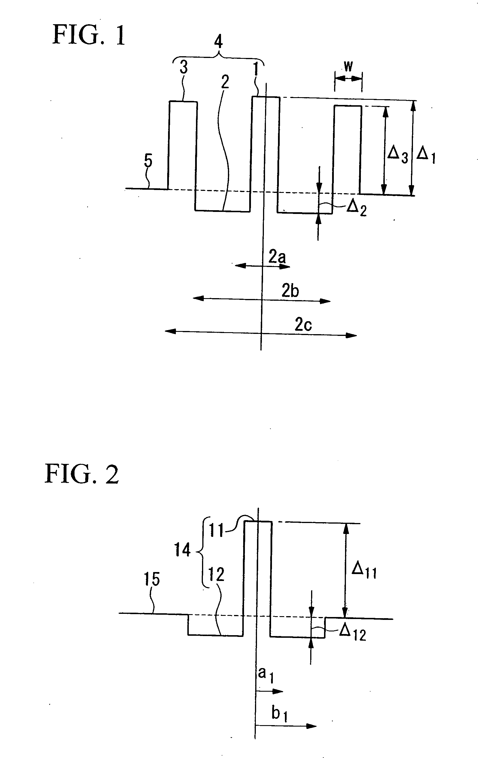
If a is less than 2 .mu.m, bending loss increases, while if a exceeds 3 .mu.m, Aeff decreases and cutoff wavelength becomes longer, thereby preventing the desired characteristics from being obtained.
If greater than 1.5%, the amount of
dopant doped to the central core portion 1 increases resulting in increased
transmission loss.
Furthermore, even if the ranges of all of these values are satisfied, there is no guarantee that a dispersion-compensating optical fiber provided with the following characteristics can be obtained.
If Aeff is less than 20 .mu.m.sup.2, non-linear effects are unable to be suppressed thereby making this disadvantageous.
If outside of this range, compensation of dispersion slope becomes inadequate, thereby possibility causing difficulties during
wavelength division multiplexing transmission and so forth.
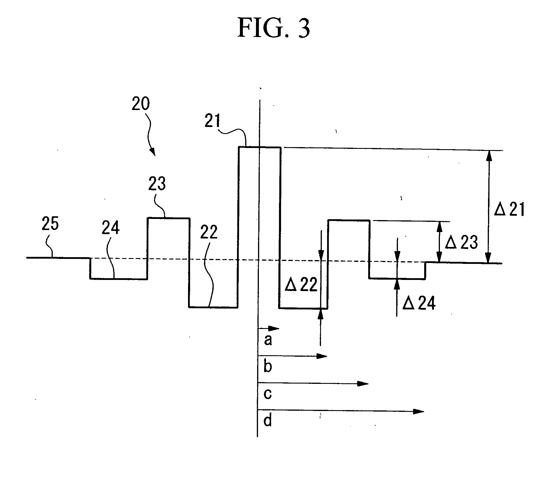
In addition, if greater than 5.0, the effect of providing intermediate core portion 12 diminishes and
trapping of the optical electromagnetic filed in the core becomes excessively strong, which tends to decrease the effect of enlarging Aeff.
If greater than 1.30%, the amount of dopant doped increases, resulting in a possible increase in
transmission loss.
If it is less than -0.50% and the amount of dopant doped increases, the amount of dopant doped of .
DELTA..sub.22 increases which may result in deterioration of
transmission loss.
In the case it is greater than -45 ps / nm / km and approaches zero, the used length becomes longer which is disadvantageous.
If chromatic dispersion is less than -70 ps / nm / km, characteristics deteriorate easily resulting in production being difficult.
If it exceeds 50 dB / m, there are cases in which transmission characteristics deteriorate due to even the slightest bending applied when laying the optical fiber and so forth.
If the side ring core portion of this dispersion-compensating optical fiber for transmission is too large, the cutoff wavelength becomes longer and the dispersion-compensating optical fiber for transmission becomes susceptible to lateral pressure.
However, if the value of .
DELTA..sub.21 is too small, the dispersion-compensating optical fiber for transmission becomes susceptible to lateral pressure.
However, since Aeff becomes smaller the larger the absolute value of chromatic dispersion, this is disadvantageous from the viewpoint of suppressing non-linear effects.
If bending loss exceeds 50 dB / m, there are cases in which transmission loss deteriorates due to micro-bending applied during manufacturing or laying, etc.
With respect to (B) above, if V2 / V1 is less than -3.5, the problem results in which transmission loss increases.
In addition, if V3 / V1 exceeds 4.5, the cutoff wavelength becomes longer, and whether V2 / V1 or V3 / V1 is too large or too small, it is no longer possible to compensate chromatic dispersion slope.
(C) above is a condition for compensating chromatic dispersion over a broad
wavelength band, and if a is too large, compensation is no longer possible over a broad
wavelength band, while if a is too small, bending loss increases thereby weakening the resistance to micro-bending.

