Method for preparing an optical fibre, optical fibre and use of such

a technology of optical fibres and gratings, applied in the field of preparing optical fibres, can solve the problems of optical fibre loss increase, standard fbg, coating application, etc., and achieve the effects of reducing the number of processing steps

Inactive Publication Date: 2004-11-25
OPTOPLAN
View PDF9 Cites 21 Cited by
  • Summary
  • Abstract
  • Description
  • Claims
  • Application Information

AI Technical Summary

Benefits of technology

0012] The carbon coated FBG should be coated with a second protective coating which protects the carbon mechanically and prevents the carbon from burning off at elevated temperatures. This secondary coating can be a polyimide, silicone or acrylate coating, or a thin metal coating such as gold.
0013] The carbon coating process can be combined with the high temperature annealing process needed to create the chemical gratings so that heating the fibre inside a chamber containing a react

Problems solved by technology

Hydrogen will also cause a loss increase in an optical fibre, which could be detrimental for FBG-based rare-earth doped fibre lasers.
However, there is no mentioning of how such a coating can be applied

Method used


Image

  • Method for preparing an optical fibre, optical fibre and use of such
  • Method for preparing an optical fibre, optical fibre and use of such

Examples


Embodiment Construction

[0015] In the following, the invention will be described with reference to illustrations, where

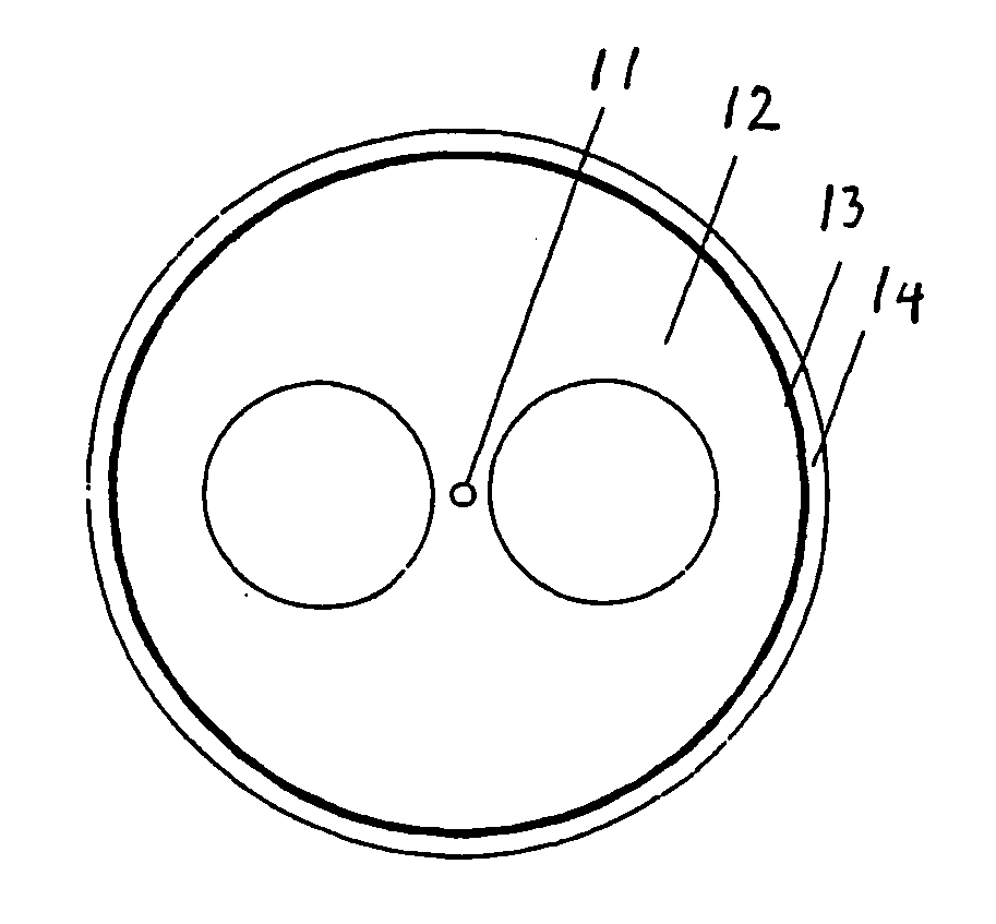
[0016] FIG. 1 shows the cross-section of a chemical FBG written in a side-hole fibre with a carbon coating and a secondary polyimide coating.

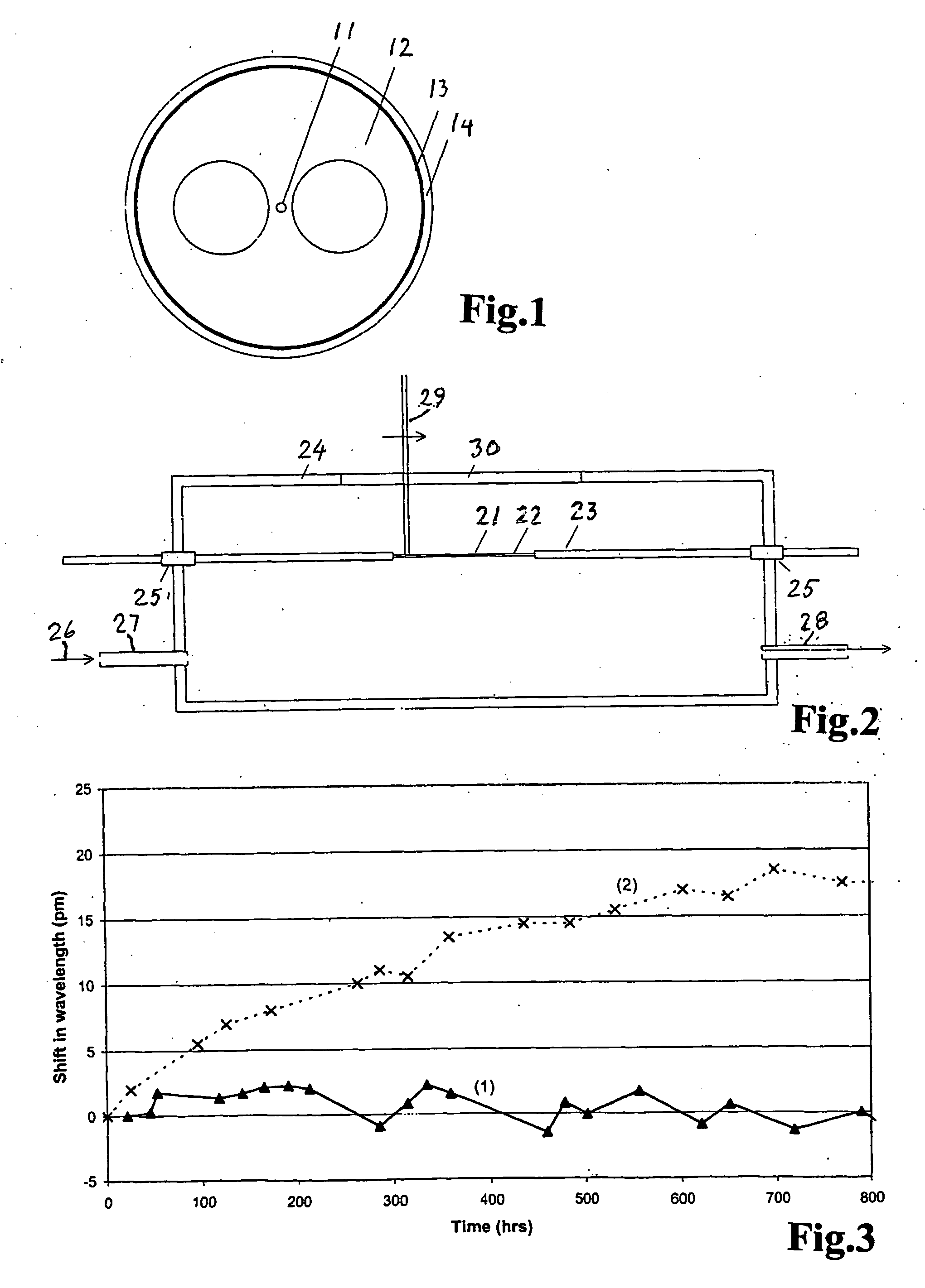
[0017] FIG. 2 is a schematic illustration of a chamber for recoating a high temperature FBG with carbon.

[0018] FIG. 3 shows the long-term drift in Bragg wavelength of a chemical FBG exposed to silicon oil at 200.degree. C., both with and without carbon recoating.

[0019] FIG. 1 shows the cross-section of a chemical FBG in the core (1) of a side-hole fibre (2) with a carbon coating (3) formed by a pyrolytic process and a secondary polyimide coating (4) to protect the carbon coated FBG.

[0020] FIG. 2 is a schematic illustration of a chamber for recoating a high temperature FBG, such as a grating, with carbon. A chemical high temperature grating (1) in a stripped section (2) of an optical fibre (3) is placed inside a sealed chamber (4). The fibre is enterin...


PUM

PropertyMeasurementUnit
Temperatureaaaaaaaaaa
Angleaaaaaaaaaa
Temperatureaaaaaaaaaa

Abstract

Method for coating an optical fibre with optical fibre Bragg grating (FBG) with a hermetic coating, particularly a coating of carbon, to avoid ingress of gases, vapours or fluids in the ambient environment. This can be water or hydrogen, which can diffuse into the fibre glass and cause deviation/drift in the measured Bragg measurements. Bragg grating that maintain the grating strength at temperatures in excess of 1000° C. is used, which is heated to above 1000 ° C. in a chamber with a reactive gas that produces deposition of carbon.

Description

[0001] The invention relates to a method for coating an optical fibre as stated in the introductory part of claim 1, as well as an optical fibre manufactured by this method, and a use of such an optical fibre.[0002] A fibre Bragg grating (FBG) is a permanent periodic refractive index modulation in the core of a single-mode optical silica glass fibre over a length of typically 1-100 mm. It can be created in a photosensitive fibre by transversely illuminating the fibre with a periodic interference pattern generated by ultra-violet (UV) laser light. The refractive index modulation in a standard FBG is believed to form by UV induced breaking of electronic bonds in Ge-based defects, releasing electrons which are re-trapped at other sites in the glass matrix. This causes a change in the absorption spectrum and in the density, and thereby a change in the refractive index of the glass. An FBG reflects light within a narrow bandwidth (typically 0.1-0.3 nm), centred at the Bragg wavelength, 1...

Claims


Application Information

Patent Timeline
IPC IPC(8): C03C25/10C03C25/22C03C25/62G02B6/02
CPCC03C25/104C03C25/1075C03C25/223C03C25/6233G02B6/02395G02B6/02104G02B6/02123G02B6/02185G02B6/02C03C25/1062C03C25/6208
Inventor KRINGLEBOTN, JON THOMASHORDVIK, AUDUN
Owner OPTOPLAN
Why Eureka
Try Eureka