Heater module for semiconductor production system

a technology of semiconductor production system and heater module, which is applied in the direction of ohmic resistance heating, heating arrangement of hot plates, coatings, etc., can solve the problems of significant improvement in heater cooling speed, prove to be a cost-increasing factor in semiconductor manufacturing, etc., and achieve the enhancement of adhesive strength of thin films, the effect of dramatic improvement of productivity

Inactive Publication Date: 2004-12-02
SUMITOMO ELECTRIC IND LTD
View PDF4 Cites 298 Cited by
  • Summary
  • Abstract
  • Description
  • Claims
  • Application Information

AI Technical Summary

Benefits of technology

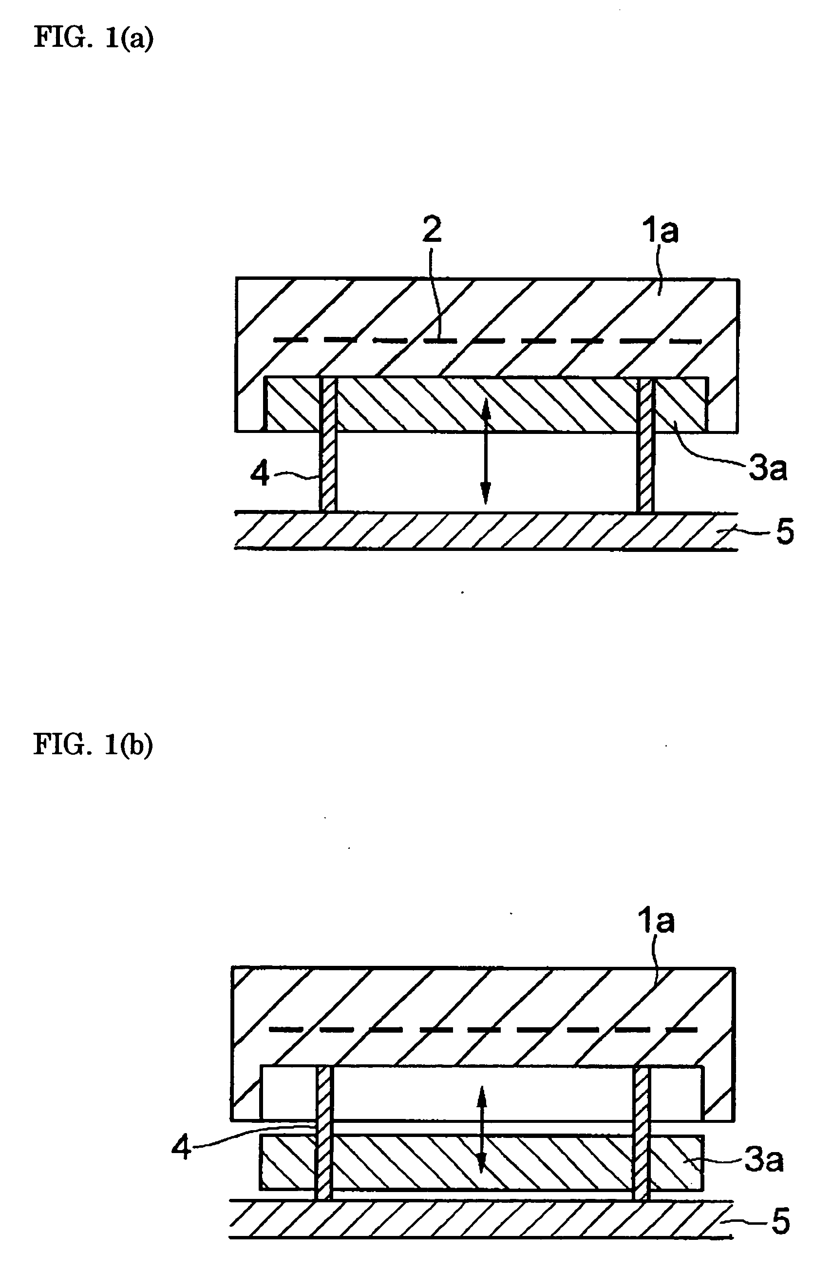
0035] The cooling speed of conventional heaters has generally been at the 1.degree. C./min level, because it has been dependent solely on radiant heat from a heater having a certain heat capacity. In contrast, in a heater module as defined by the present invention the cooling speed of the heater part, although it depends on the heat capacity of the block part, is enhanced to at least several times the conventional level. Specifically, cooling speeds of 10.degree. C./min or more can be achieved if the heat capacity of the block part is designed to be 20% or more of the total heat capacity of the heater part and the block part, enabling productivity to be dramatically improved. What is more, such improvement in cooling speed means that in terms of wafers, enhancement in the adhesive strength of thin films, enhancement in mechanical hardness, and enhancement in etching characteristics can be anticipated.
0036] Another consideration is that in situations where a heater is cooled by heat radiation, with cooling speed being influenced by surface area, the temperature in the vicinity of the heater lateral side has a greater tendency to drop because the surface area there is generally large compared with the middle portion, and during cooling the isothermal quality is consequently liable to deteriorate. With

Problems solved by technology

Nevertheless, with these forcible liquid cooling and air cooling systems, the fact that large-scale devices are necessary for circulating the heat-transferring medium and for radiating heat has proved to be a cost-increasing factor

Method used


Image

  • Heater module for semiconductor production system
  • Heater module for semiconductor production system
  • Heater module for semiconductor production system

Examples


embodiment 1

[0039] Sets of two disks 335 mm diameter and 10 mm thickness made of the ceramic materials set forth in the table below were prepared, and on the top face of one disk in each set a heating element was formed by tungsten metallization. Onto this ceramic disk the remaining ceramic disk in each set was overlaid, putting the heating element into a sandwich which was then hot-press joined using a hot press device, whereby ceramic heater parts were fabricated.

[0040] Block parts, made from each of the metal and ceramic materials set forth in the following table and having the same diameter as the foregoing heater parts, were also fabricated. In doing so, the percent heat capacity of the block part with respect to the total heat capacity of the heater and block parts was varied as indicated in the table below by varying the block part thickness. In addition, in all samples, the top face of the block part (the face where it abuts with the heater part) was surfaced by lapping.

[0041] Heater mo...

embodiment 2

[0046] A heater module was assembled utilizing the same heater part and block part as with Sample 4 in the foregoing Embodiment 1, but the reverse face of the AlN-made heater part--i.e., the face where it abuts with the Al-made block part--was covered with a Cu layer 0.2 mm in thickness.

[0047] The same testing and evaluation as with Embodiment 1 were performed on this heater module, with the result being that the heater cooling speed and the isothermal rating were the same as with Sample 4 in Embodiment 1. With Sample 4 in Embodiment 1, however, at 500 cycles chips 0.1-0.2 mm in diameter appeared in the edge of the reverse face of the heater part, but with the present Embodiment 2 sample, no chips or like flaws were discernable at all.

embodiment 3

[0048] A heater module was assembled utilizing the same heater part and block part as with Sample 4 in the foregoing Embodiment 1, but the top face of the Al-made block part--i.e., the face where it abuts with the AIN-made heater part--was finished to a specular surface by a polishing process.

[0049] The same testing and evaluation as with Embodiment 1 was performed on this heater module. Thanks to the top face of the block part having been made mirror-like, heat radiant from the heater part was reflected back, keeping the block part from absorbing the heat, and therefore even with the separation between the heater part and the block part curtailed to 50 mm, the same heater cooling speed and isothermal rating as with Sample 4 in Embodiment 1, where the heater part-block part separation was set at 200mm, were obtained.


PUM

PropertyMeasurementUnit
Fractionaaaaaaaaaa
Fractionaaaaaaaaaa
Fractionaaaaaaaaaa

Abstract

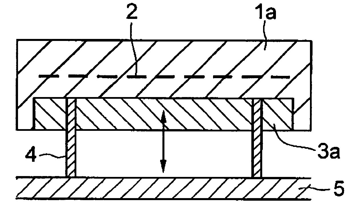
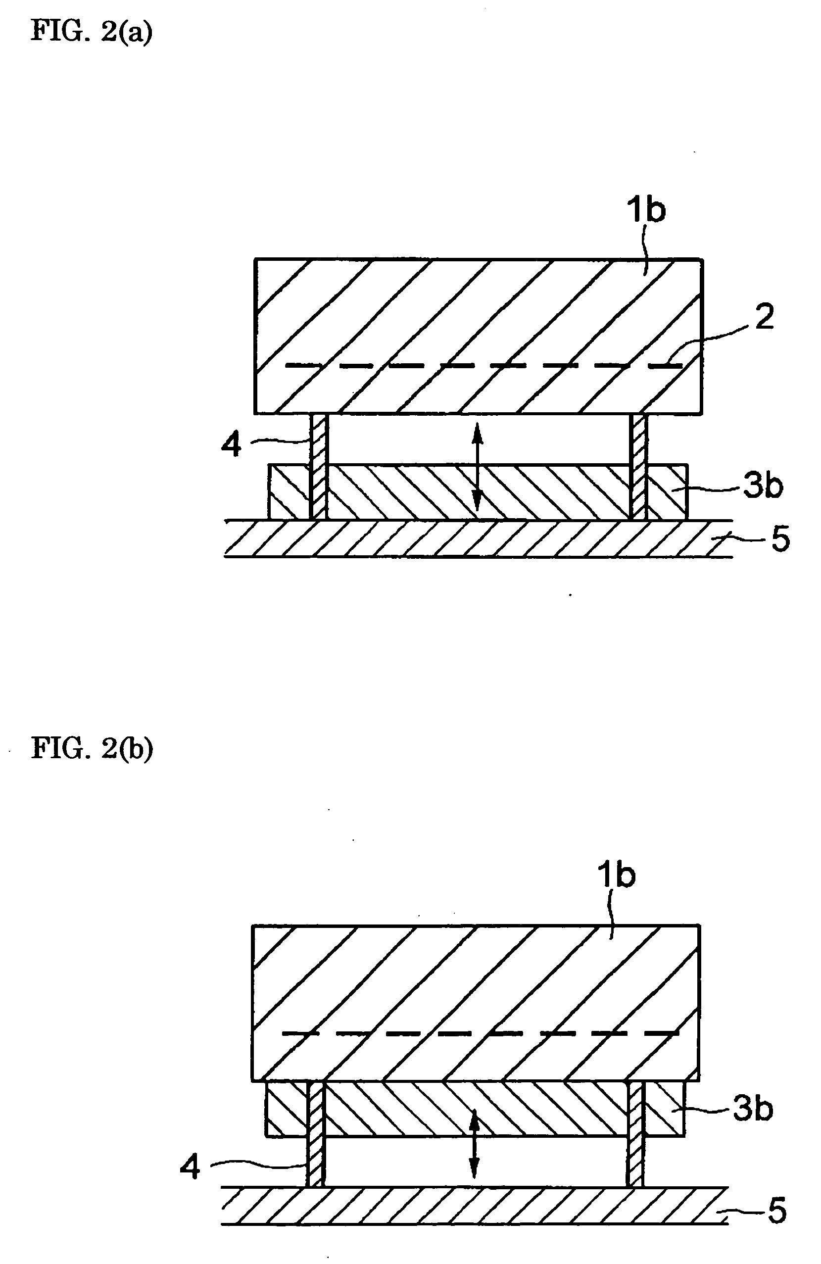
Heater module, and semiconductor manufacturing equipment in which the heater module is utilized, for raising the cooling speed of a post-heating heater markedly more than conventional, and that can contribute toward bettering and improving productivity, without accompanying scaling-up of and cost increases in the semiconductor manufacturing equipment. The heater module is furnished with heater part 1a for controlled heating of a wafer placed on its top face, and block part 3a provided to be shiftable relative to said heater part, for varying heat capacity in total with heater part 1a by abutting on or separating from the reverse surface of heater part 1a. By having the heat capacity of block part 3a be 20% or more of the total heat capacity of heater part 1a and block part 3a, the heater cooling speed can be made 10° C./min or more.

Description

[0001] The present invention relates to heater modules, utilized in semiconductor manufacturing tools that process semiconductor wafers, for semiconductor manufacturing equipment capable of heat-treating and cooling wafers, and to semiconductor manufacturing equipment in which such heater modules are installed.[0002] In the course of semiconductor fabrication, processes in which after being treated by heating wafers are cooled include: thermosetting of photoresists in photolithography with coater / developers; heating / baking of low-dielectric-constant, i.e. low-k, insulating films; CVD film deposition in forming metal interconnects and dielectric layers; and processes in etchers.[0003] Heat-treatment of the wafers in these processes has conventionally been carried out using heaters made of aluminum or ceramic. In particular, wafers are placed onto the outer face of heaters in which a heating element is formed, utilized to control heating while the wafers undergo processes such as ther...

Claims


Application Information

Patent Timeline
IPC IPC(8): H01L21/00C23C16/46H01L21/205H01L21/3065
CPCH01L21/67109H01L21/02
Inventor KUIBIRA, AKIRANAKATA, HIROHIKO
Owner SUMITOMO ELECTRIC IND LTD
Why Eureka
Try Eureka