
Modular mobility unit

a technology of mobility unit and module, which is applied in the direction of electric propulsion mounting, wheelchair/patient conveyance, transportation and packaging, etc., can solve the problems of many difficulties in daily life for handicapped people who cannot stand or otherwise lift their weight with their arms, and are often lifted and transferred between wheelchairs

Inactive Publication Date: 2004-12-16
PATTERSON RICHARD A
View PDF8 Cites 19 Cited by
  • Summary
  • Abstract
  • Description
  • Claims
  • Application Information

AI Technical Summary

Benefits of technology

[0030] It is yet another object of the present invention to provide a modular mobility unit which simplifies manufacturing concerns with regard to the handedness of the unit.
[0034] Advantageously, when the center module contains a lift and transfer mechanism, it is constructed with the center of operation of the lifting arm equidistant between the front and rear mounting surfaces of that module such that the center section of the chair can be assembled in either a right-hand or left-hand manner. Thus, if an individual's living needs change and it becomes necessary to alter the handedness of the lift / transfer / elevate chair, this change can easily be implemented by a service technician. This approach similarly allows the modular mobility unit to be assembled in a manufacturing facility for use as either right-or left-hand operation against any customer orders. The versatility and functionality of the modular mobility unit enables one basic modular product platform to be configured as a large number of different individual products, each with specific capabilities and each upgradeable or field re-configurable to other products. These products can vary not only with regard to the handedness of the chair, but additionally with regard to other features. If the user purchased a modular mobility system in which the center module was only a spacer and seat support to meet his current needs for transport only and at some point in the future this person's condition changes and he is now unable to manually lift and transfer himself from his transporter unit into his furniture or bed, then the modular mobility system that he initially purchased could be easily upgraded by a technician in the handicapped person's home. The blank center section of the original unit is removed at its mounting interfaces, and a center module containing a lift and transfer arm and docking station is put in its place. All of the other modules of the original transporter unit could still be used. The field upgrade would now provide the handicapped person with a single mobility system that could transport him in and outside his residence, raise him to reach elevated objects, and lift and transfer him to and from his transporter unit. The cost to the insurer of utilizing much of the handicapped person's original transporter device, and only upgrading it to have lift and transfer capability it expected to be a much more cost effective way to quickly meet the handicapped person's changing mobility needs.

Problems solved by technology

While about half of these people are able to stand on their own, the remaining half are unable to support their weight on their legs.
Handicapped people who are unable to stand or otherwise lift their weight with their arms face many difficulties in their daily lives.
One of the most serious of these is that they must be frequently lifted and transferred between their wheelchairs and their beds, regular chairs, dining facilities, bathroom fixtures, cars, etc.
Occasionally, commercially available lifting aids are employed to assist with patient lifting, but because of limitations and ease of use issues, most patient lifting and transfers are done manually.
Whenever disabled individuals are lifted or moved, there is a possibility for injuring that person.
These injuries usually result when the patient is bumped into objects while being lifted and transferred, or from being dropped.
When caregivers manually lift and transfer patients, they can seriously injure their backs.
Often the patient being lifted is significantly heavier than the care giver, and cannot assist the care giver during the move.
Some patients also move erratically while being moved, and may slip out of the care givers grasp, or force the care giver to quickly readjust their lifting position.
If they are unable to perform these functions due to lifting injuries to the back, they may be required to work in other capacities in the health care system, or to find other jobs.
The loss of skilled experienced nurses and care givers in nursing homes, hospitals, and hospice institutions reduces the overall quality of healthcare delivered.
The reporting process and subsequent review sessions, although worthwhile, result in significant additional effort and cost on the part of the nursing institution.
In home care settings, a significant portion of the cost of caring for a seriously handicapped individual is the cost of care givers who are required to safely lift and move the patient.
Another problem confronted by people with serious physical disabilities is the occurrence of pressure or bed sores when the patient is allowed to remain in one position for extended periods of time.
Pressure sores are painful and very difficult and expensive to cure.
It is often difficult for challenged people to make the transition from being totally independent, to being highly or totally dependent on caregivers for the most basic functions.
The combination of these two factors can lead to the onset of serious depression in the individual, and thus reduce the rate of their recovery.
However, these devices and systems have serious short comings, and do not address the total need associated with safely lifting, transferring, and transporting handicapped individuals within their daily living and healthcare environments.
Although it would be possible to move the patient hoist between lifting locations, these types of lifting devices are awkward to move, and are designed primarily for use in one location.
The devices are relative large, and take a considerable amount of floor space.
However this can be demoralizing and degrading for patients to be dangling from the end of a chain in a sling while being moved in public places, and this form of patient transport is normally not done.
Another significant disadvantage of hoist devices is that the lift starting position, patient's trajectory or path during the move, uniformity of motion, and end landing position are all controlled manually by the care giver.
One final disadvantage of lifting hoists is that they are not designed so the user cannot operate the hoist themselves.
Thus, handicapped individuals who are seeking greater independence from caregivers still will require another person to operate the lifting hoist style patient transfer device.
Another patient lift and transfer system is available for use in homes and institutional settings, referred to as an overhead hoist / trolley system, which also has significant limitations and drawbacks.
It is clearly not possible to transfer a patient in any indoor or outdoor location where the overhead lifting track is not in place.
Accordingly, the overhead track system could not be used for transferring a patient from his wheelchair into a car for example.
Another limitation of the track patient lift system relates to installation of the system in a home or institution.
They do not however enable a patient to be lifted and transferred between wheelchairs, furniture, cars, and the like.
Another problem with mobility devices that are available today is that there is no single device that can provide all the major mobility functions required by handicapped persons.
Powered wheelchairs can transport a person in and outside his residence but cannot lift and transfer the person.
Lifts can lift and transfer a person to and from his wheel chair, but cannot transport him within his residence.
There is a further problem with the "handedness" of some mobility systems, i.e., they are constructed with an asymmetrical design which allows elevating or transferring to only one side of the wheelchair.
Such a construction may present difficulties when the user is in a setting which requires elevation or transfer to the left side.
Current mobility systems are not versatile enough to allow deployment on either side.
Unfortunately, current transfer chairs do not allow for either factory or field conversion from right-hand lifting capability to left-hand.
The handedness of a transfer chair can additionally create problems with regard to the manufacturability of the chair.
Although separate parts can be provided, it increases the amount of engineering required for design of the chair, and also increases the amount of inventory of separate types of parts that the manufacturer must maintain in stock to provide both right- and left-hand chairs against orders.
A final problem with mobility devices that exist today is that they cannot be upgraded to meet the mobility needs of their users as these needs change.
Powered wheelchairs for example cannot be modified or upgraded to provide lift and transfer capability as the user becomes less able to move himself.
Usually it is necessary for the handicapped person to purchase additional separate pieces of equipment, and / or to rely more heavily on caregivers which substantially increases the cost of care.

Method used


Image

  • Modular mobility unit
  • Modular mobility unit
  • Modular mobility unit

Examples


Embodiment Construction

)

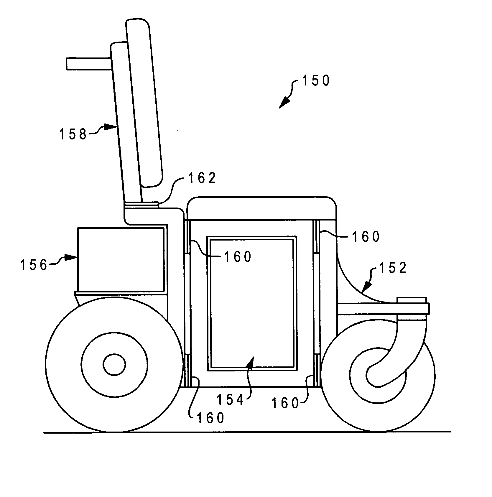
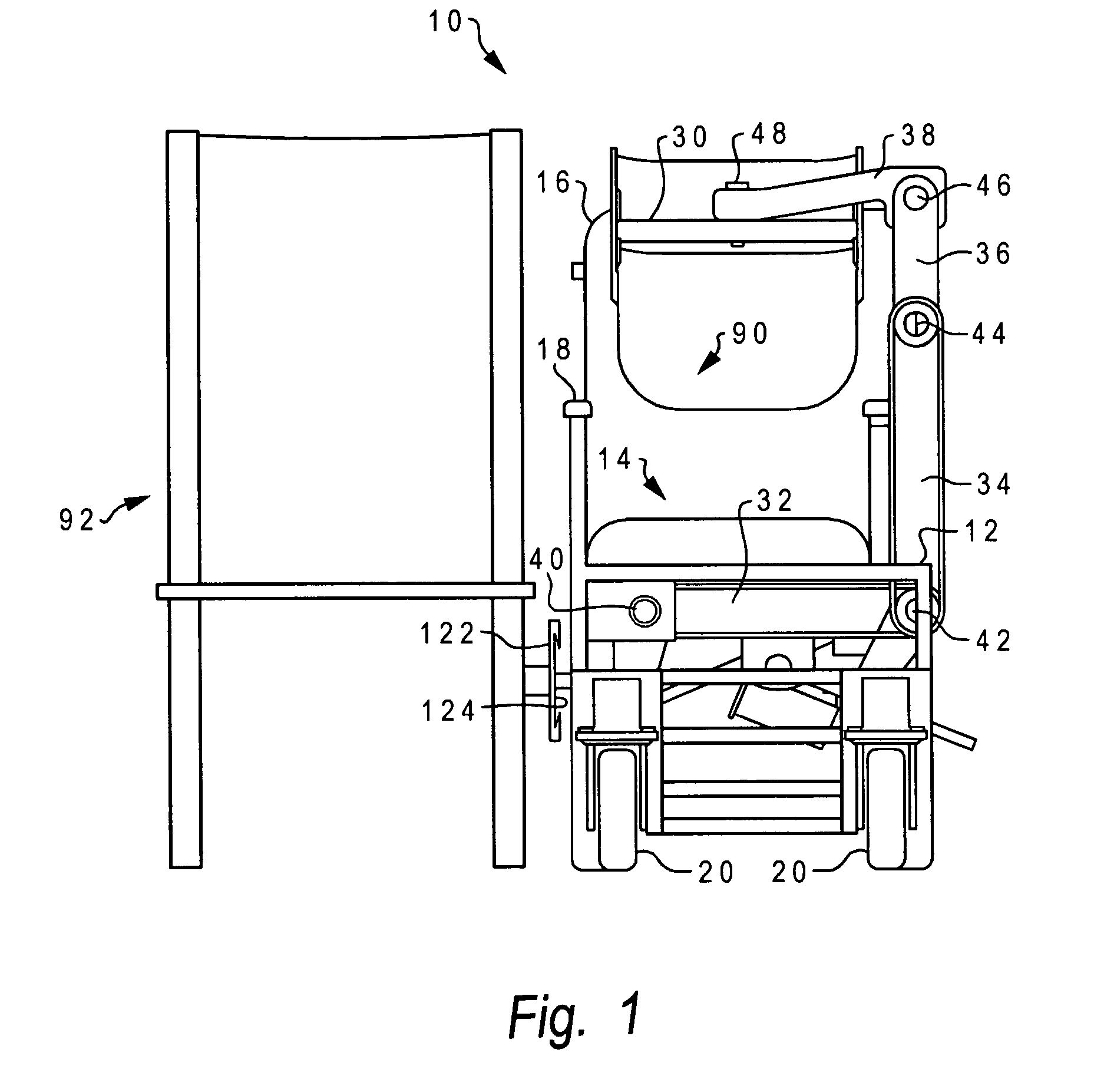
[0045] With reference now to the figures, and in particular with reference to FIG. 1, there is depicted one embodiment 10 of a lift and transfer chair constructed in accordance with the present invention. Lift transfer chair 10 is generally comprised of a chassis or frame 12, a seat 14 attached to frame 12, a chair back 16 attached to frame 12, arm rests 18 attached to frame 12, and wheels 20 operably mounted to frame 12. The outside of the chair chassis is covered by panels for the user's safety, and for protection of and access to internal components. In the illustrative embodiment, the lift transfer chair is designed to fit through a 24 inch door opening, and has the same approximate outside dimensions as currently available electric wheelchairs (23.5 inches wide.times.30 inches long.times.36 inches high). This embodiment has an electric drive (i.e., motor and gears) to impel chair 10 so wheels 20 are relatively small, but a manual drive version can be designed with larger rear ...


PUM


Abstract

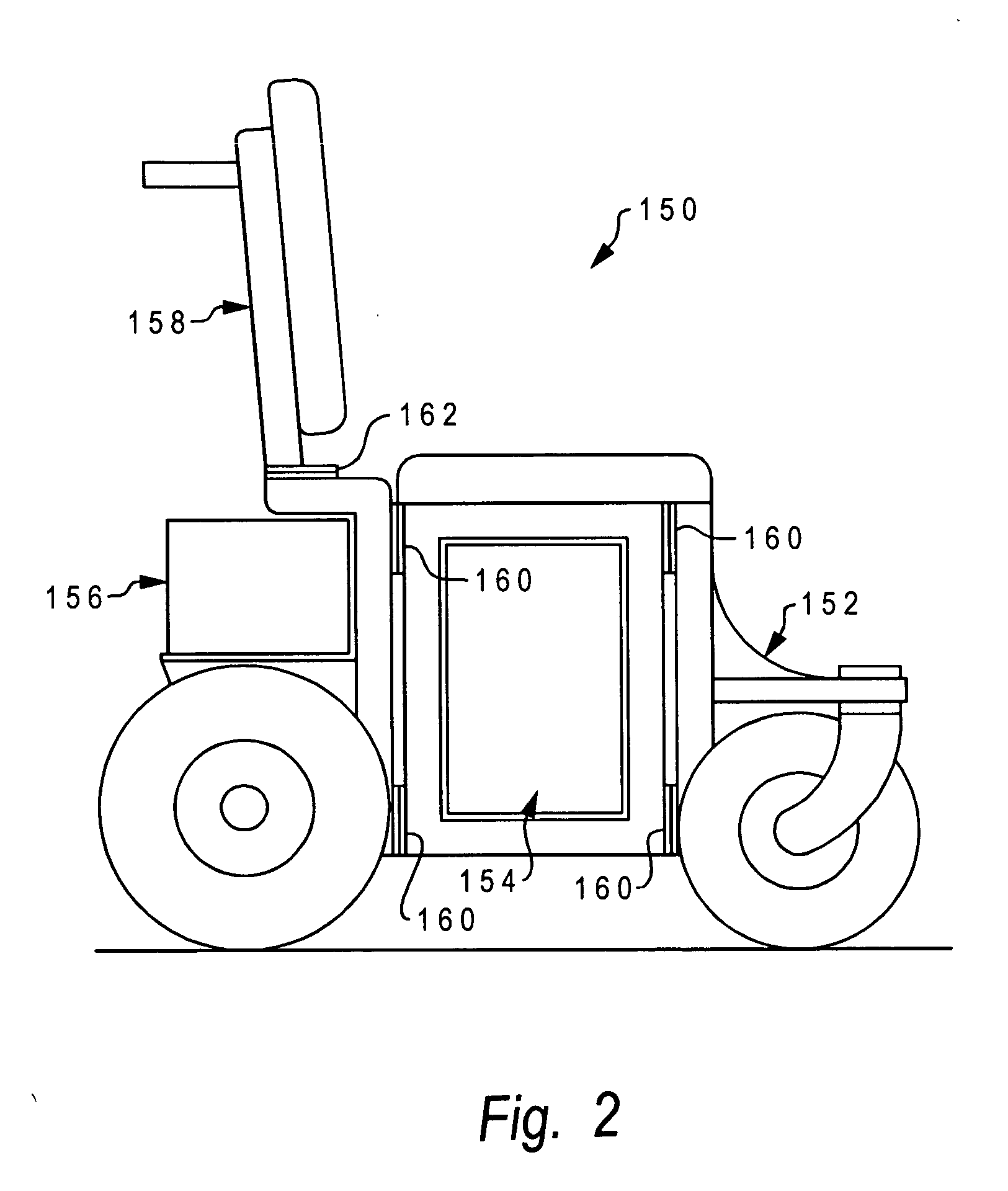
A mobility unit uses several modular components that allow the unit to be assembled or re-configured into one of a number of different product designs. Four such modules may include a front module which houses the front pivoted casters or wheels and foot rests, a center module which provides the lifting / transfer / elevate functions, a propulsion module having the rear wheels, variable speed / reversible gear drive motors, batteries, and a chair control computer, and a rear module which contains the seat back cushion and support, and any push handles and controls for operation by an caregiver. Mechanical interfaces are designed to accommodate the interconnection of the modules in various configurations. Advantageously, the central lifting module is adapted to function in either a right-hand orientation or a left-hand orientation. The versatility and functionality of the modular mobility unit enables one basic modular product platform to be configured as a large number of different individual products, each with specific capabilities and each upgradeable or field re-configurable to other products. These products can vary not only with regard to the handedness of the chair, but additionally with regard to other features.

Description

[0001] This application is a continuation-in-part of U.S. patent application Ser. No. 10 / 460,602 filed on Jun. 12, 2003, which is hereby incorporated.[0002] 1. Field of the Invention[0003] The present invention generally relates to mobility enhancement systems for physically challenged individuals, and more particularly to wheelchairs which allow the user to be elevated or transferred to a position adjacent the wheelchair, and modular constructions for wheelchairs.[0004] 2. Description of the Related Art[0005] In the United States alone, there are over three million physically challenged individuals who are confined to wheelchairs due to illness, accidents or degenerative diseases. While about half of these people are able to stand on their own, the remaining half are unable to support their weight on their legs. Approximately 80% of people using wheelchairs are cared for in their own homes, while the remainder are cared for in nursing homes, hospice facilities, rehabilitation cente...

Claims


Application Information

Patent Timeline
Patent Type & Authority Applications(United States)
IPC IPC(8): A61G3/02A61G5/04A61G5/10A61G7/10
CPCA61G3/0209A61G5/043A61G5/045A61G5/10A61G7/1017A61G7/1053A61G7/1059A61G2200/34A61G2203/44
Inventor PATTERSON, RICHARD A.PATTERSON, ALAN D.PATTERSON, ROY M.SKRABA, JOSEPH S.
Owner PATTERSON RICHARD A
Learn More