Apparatus and method for nanoparticle and nanotube production and use therefor for gas storage

a technology of apparatus and nanotubes, which is applied in the direction of mechanical apparatus, energy-based chemical/physical/physicochemical processes, and fullerenes. it can solve the problems of low yield of lower and higher fullerenes, affecting the production of nanotubes on a commercial scale, and affecting the production of nanotubes. it achieves the effect of avoiding saturation of the arc gap and increasing yield

Inactive Publication Date: 2004-12-23
ROSSETER HLDG
View PDF4 Cites 28 Cited by
  • Summary
  • Abstract
  • Description
  • Claims
  • Application Information

AI Technical Summary

Benefits of technology

0026] In WO-A-00/61492, the applicants describe a device and method for producing higher fullerenes and nanotubes. The apparatus described in this application comprises a sealed chamber containing opposite polarity carbon (graphite) electrodes. The first electrode (electrode A) consists of a graphite pipe which is installed in vertical cylindrical openings of the cylindrical graphite matrix that forms electrode B. A free moving spherical graphite contactors is positioned ab...

Problems solved by technology

However, production of nanotubes on a commercial scale still poses difficulties.
Despite outstanding results obtained with laser ablation [1], one can conclude that any process and apparatus based on laser ablation is not commercially viable because of the very low coefficient (few %) of transformation electric energy to energy deposited into vaporized targets.
The main problem is a very low yield of the lower and higher fullerenes.
As a result, the amounts of such fullerenes available are too low to study their general properties.
HPLC is characterized by a very low production of higher fullerenes and, as a result, market prices of the higher fullerenes are enormous, more than $1,000-10,000 per gram.
Therefore, usual inert gas arc methods are useless for producing higher fullerenes.
However, neither fullerenes greater than C.sub.76, nor nanotubes/nanoparticles were produced this way.
The process also consumes a lot of electric energy as the high-voltage arc is used.
Under such arcing, tips of the electrodes are "exploded" causing graphite or metallic (if metallic electrodes are used) debris in the products.
The great disadvantage of this methodology is that the process is not self-regulated.
In such a device the tips of the electrodes will be destroyed after few "explosions".
In observing Modak's method a safety problem arose because of the release of huge amounts of gases in the process of cracking benzene/toluene.
Another problem of the Modak method is that there are no means (for example, an additional buffer gas with the exception of gaseous hydrocarbons released under cracking the liqu...

Method used


Image

  • Apparatus and method for nanoparticle and nanotube production and use therefor for gas storage
  • Apparatus and method for nanoparticle and nanotube production and use therefor for gas storage
  • Apparatus and method for nanoparticle and nanotube production and use therefor for gas storage

Examples


example 2

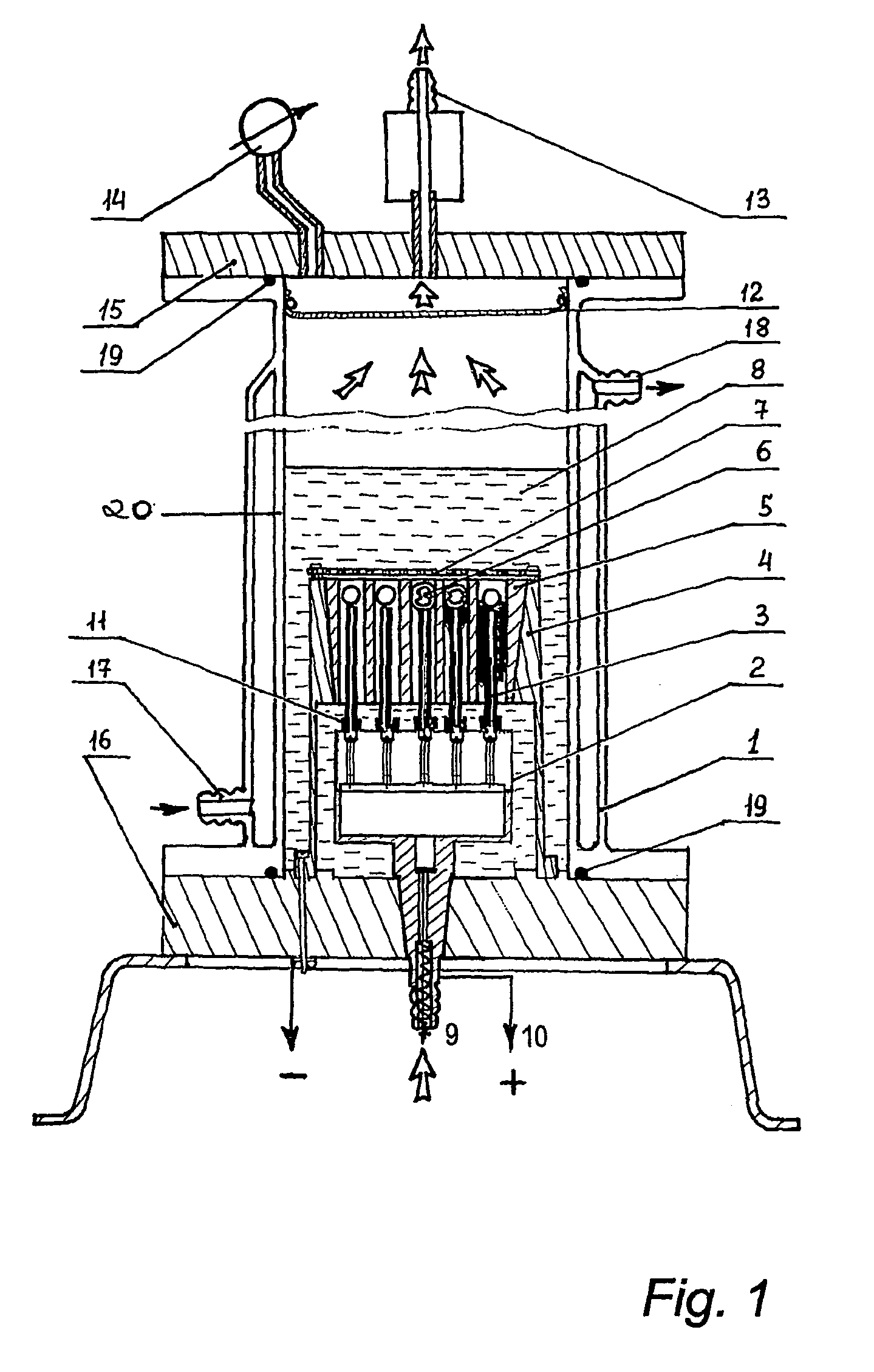
Producing Nanotube / Nanoparticle Deposits with an AC Power Supply Using the Apparatus of FIG. 1.

[0190] Apparatus 1 can be used (FIG. 1) to produce nanotube deposits over the electrodes 3,5.

[0191] The body is filled by an aromatic liquid 8, like benzene, toluene, xylenes, Co- and Ni-naphtenates based on toluene etc., or their mixtures to a level that is, at least, enough to cover the contactors 6.

[0192] Before the reaction commences, air is pumped out from the body through the outlet of a safety valve 13 and pure argon gas is pumped through the inlet 9 and through the pipes 3 (electrode A) to fill the empty space to a pressure that is optimal for producing carbon nanotubes / nanoparticles, most preferably, in the range of 600-800 Torr. Afterwards, an argon flow through the opening is maintained in the range of 1-3 liter per hour per a pair of electrodes, i.e. about 20-60 liters per hour for this apparatus.

[0193] As soon as the power supply 10 is switched on the process starts. With a no...

example 3

Producing Nanotube / Nanoparticle Deposits with a DC Power Supply Using the Apparatus of FIG. 1.

[0203] DC power supplies appear to be more preferable for producing nanotube / buckyonion deposits. FIG. 6 shows an experimental dependence of the deposits compositions and their yields versus a DC voltage applied. From this dependence one can see that in this apparatus producing nanotube / nanoparticle deposits starts at voltage of about 20 V.

[0204] The most preferable voltage for producing MWNTs is within the range from 24 to 30V with the deposits' yields of 0.4-1.0 g / min, correspondingly. Increasing applied voltages over 36V are likely to increase yields of buckyonions, graphite and metal clusters.

[0205] Increasing the applied voltage over 28-30 Volts requires putting one or two additional contactors above the usual one to maintain optimal arcing (these additional contactors are not eroded at all and may be used many times).

[0206] There are two different kinds of deposits, "hard" shells and ...

example 4

Producing Nanotube / Nanoparticle Deposits Using the Apparatus of FIG. 13

[0226] The apparatus for producing fullerenes illustrated in FIG. 13 includes a hermetically sealed chamber 21, in which a holder 22 of the electrodes A 23 and a holder 24 of the electrode B 25, and fixed spherical or hemisherical graphite contactors 26 are situated below the electrodes A 23 above a metallic grid 27. This arrangement is immersed in a hydrocarbon liquid 28 and is connected to a valve 29 (for adding a buffer gas into the chamber 1 around the electrodes), and to a standard AC power supply 30 typically used for welding (three phase voltage, 53V, 50 Hz).

[0227] Cylindrical rods 23 (electrodes A) with a smaller diameter are installed in holder 22 by using cylindrical ceramic insulators 31 and are connected to the holder using safety wires. The rods 23 are axially installed inside a vertical cylindrical opening of a graphite matrix 25 (electrode B).

[0228] FIG. 13 shows a design of the apparatus with 19 p...


PUM


Abstract

There is provided a method for the enhanced production of fullerenes, nanotubes and nanoparticles. The method relies upon the provision of a hydrocarbon liquid which is converted by a suitable energy source to a synthesis gas such as acetone, ethylene, methane or carbon monoxide, the synthesis gas(es) forming the precursors need for fullerene, nanotube or nanoparticle production. The nanotubes formed by the method described are in general terms shorter and wider than conventionally produced nanotubes. An improved apparatus for production of the fullerenes and nanocarbons is also disclosed wherein a moveable contactor is attached to a first electrode with a sealable chamber, and is spaced from the second electrode such that an electric arc can pass between them.

Description

APPLICATION CROSS-REFERENCES[0001] This application claims priority of International Application No. PCT / GB02 / 04049 filed Sep. 6, 2002 and published in English. This application also claims priority of Great Britain Patent No. 0121558.1, filed Sep. 6, 2001, and of Great Britain Patent No. 0121554.0, filed Sep. 6, 2001, and of Great Britain Patent No. 0123491.3, filed Sep. 29, 2001, and of Great Britain Patent No. 0123508.4, filed Oct. 1, 2001.BACKGROUND OF INVENTION[0002] The invention concerns the production of new carbon allotropes, namely, fullerenes, carbon nanotubes and nanoparticles (buckyonions), and also the encapsulation of such gases inside such nanocarbons (particularly nanotubes, nanohorns, nanofibers and other nanoporous carbons) for storage purposes.[0003] Carbon nanotubes are fullerene-like structures, which consist of cylinders closed at either end with caps containing pentagonal rings. Nanotubes were discovered in 1991 by Iijima [15] as being comprised of the materi...

Claims


Application Information

Patent Timeline
IPC IPC(8): B01J19/08C01B3/00C01B23/00C01B31/02F17C11/00
CPCB01J19/088B01J2219/00087B01J2219/0809B01J2219/0822B01J2219/0828B01J2219/0839B01J2219/0871B01J2219/0875B01J2219/0877B82Y30/00B82Y40/00C01B3/0021C01B23/00C01B31/0213C01B31/0233C01B2202/02C01B2202/06F17C11/00F17C11/005F17C11/007Y02E60/321Y02E60/325C01B32/162C01B32/154C01B32/156Y02E60/32B82B3/00
Inventor RYZHKOV, VLADISLAY ANDREEVITCH
Owner ROSSETER HLDG
Why Eureka
Try Eureka