
Probe Beads for affirnity reaction and detection system

a technology of probe beads and amplification, applied in the field ofaffinity reaction probe beads, can solve the problems of high cost, lack of analytical means for giving, and high cost, and achieve the effect of stable deterioration or falling o

Inactive Publication Date: 2005-01-06
EBARA CORP
View PDF0 Cites 23 Cited by
  • Summary
  • Abstract
  • Description
  • Claims
  • Application Information

AI Technical Summary

Benefits of technology

According to the present invention, porous beads are used as carriers, whereby the surface area usable for immobilization of probes is large relative to the size of the beads, so that large amounts of probes can be bound to the beads. Moreover, the probes are immobilized on the internal surfaces of the pores within the carrier. This confers the advantage that the probes are unsusceptible to physical and chemical influences, and are stable to deterioration or falling-off.

Problems solved by technology

However, this affinity detection method in liquid chromatography merely gives information on a single particular molecule or a small number of particular molecules, and is not an analytical means for giving information on the presence of many molecules at the same time.
To secure such numerous cDNA's, a lot of time and huge expenses are required.
These affinity reaction probe methods involving chips are very effective as analytical means giving information on the existence of many molecules at the same time, but posed several problems.
Moreover, a procedure comprising 4 cycles of photolithography, coupling and washing is repeated to cover the required chain length, thereby resulting in a high cost.
Thus, it was impossible to prepare DNA chips of various designs flexibly fulfilling needs.
In addition, synthesis took place while using one photomask at a time and performing one stage at a time, so that the grade of each spot was not ensured, thus posing the problem that chip-to-chip reproducibility remained insecure.
However, the step of spotting probe molecules, spot by spot, onto immobilization glass or the like must be carried out, thus presenting the drawback of leading to a high cost as does the DNA chip using photolithography.
At the time of detection by reaction chips comprising these DNA microarrays, moreover, hybridization was localized, and definitive determination was not possible any more.
Hence, detection of various pieces of genetic information, including those on bone marrow transplantation, involved enormous labor, took much time, and cost heavy expenses.
Furthermore, the identifications based on analog information, such as information on the types and densities of colors, cannot completely avoid read errors.
The probes so bound to the surface of beads are susceptible to external physical and chemical influences, and the probes are prone to fall off or deteriorate, making them unstable.
Since immobilization has taken place only on the surface of the beads, moreover, there is the drawback that the probe binding area of the carrier is small.

Method used


Image

  • Probe Beads for affirnity reaction and detection system
  • Probe Beads for affirnity reaction and detection system
  • Probe Beads for affirnity reaction and detection system

Examples


example 2

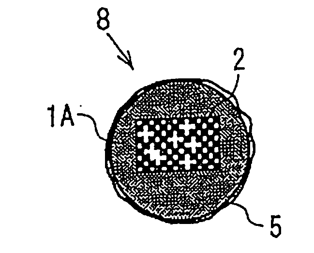
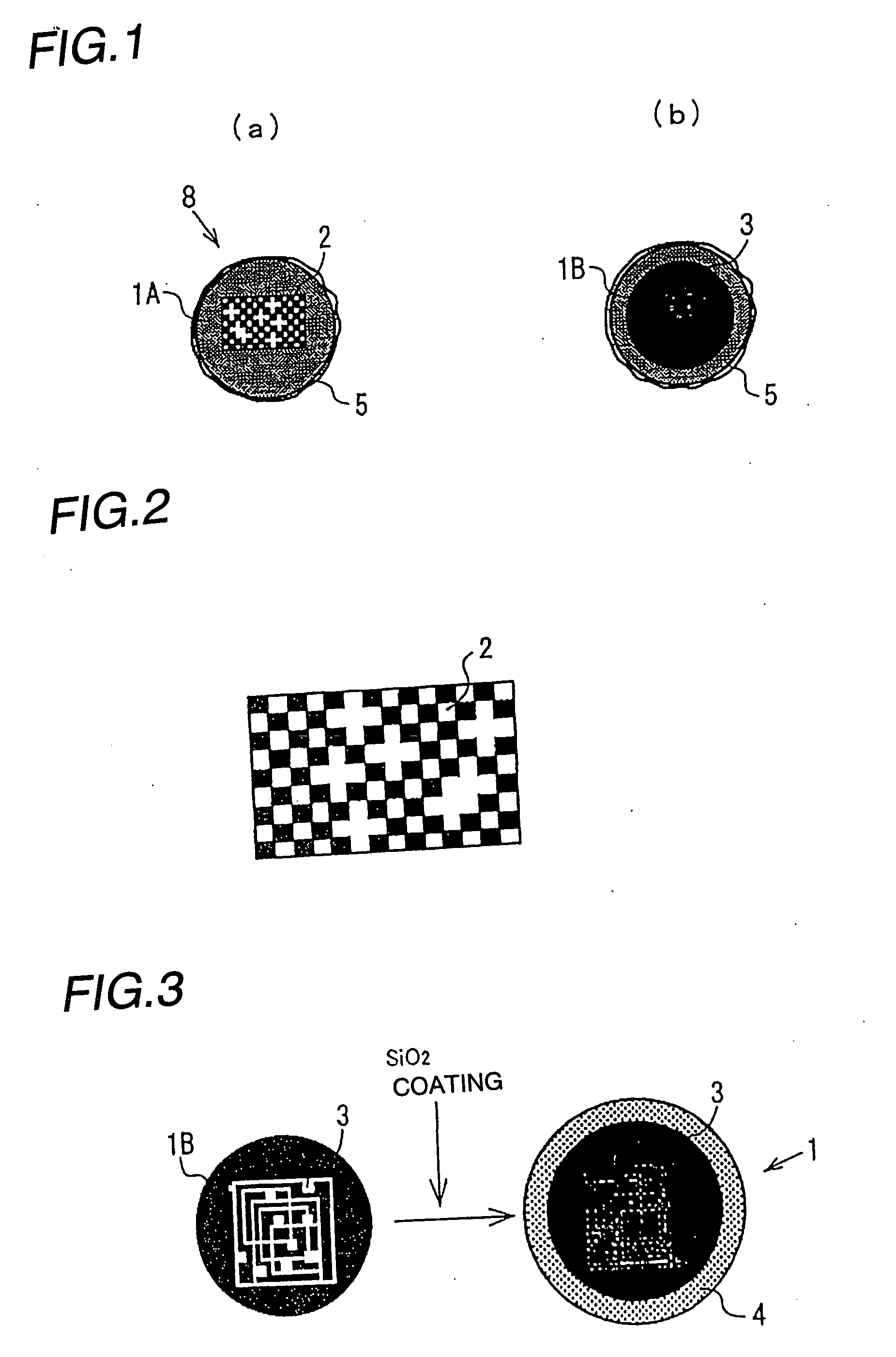
IC tag identification marks composed of certain resonance circuits were formed on single crystal spheres of silicon having a diameter of 0.5 mm. These spheres were each coated with a silica membrane formed by hydrolysis of tetraethoxysilane. The resulting carriers were treated with epoxysilane, which was used as a linker to immobilize particular cDNA's on the carriers.

The thus produced affinity reaction probe beads were placed in a reaction cell of polypropylene, and a sample containing fluorescence-labeled cDNA as an object to be detected was poured into the reaction cell, thereby performing the reaction. After completion of the reaction, the system was washed, and the reaction probe beads were withdrawn from the cell. The reacted probe beads were analyzed, one by one, by a fluorescence detector and, at the same time, individually identified based on resonance frequencies.

example 3

An individual identification information circuit comprising a certain antenna circuit and an 8-bit writable ROM was formed on each of single crystal spheres of silicon having a diameter of 1 mm. After a protective film was formed on the surface of the spherical silicon, the system was treated with a cuprammonium rayon solution, and also treated with hydrochloric acid to form carriers having a regenerated cellulose layer on the surface. Particular antibodies were adsorbed to and carried on the carriers to prepare affinity reaction probe beads.

The thus produced affinity reaction probe beads were placed in a reaction cell of polypropylene, and a sample containing fluorescence-labeled protein as an object to be detected was poured into the reaction cell, thereby performing the reaction. After completion of the reaction, the system was washed, and the reaction probe beads were withdrawn from the cell. The reacted probe beads were analyzed, one by one, by a fluorescence detector and, a...


PUM

PropertyMeasurementUnit
affinityaaaaaaaaaa
affinity reaction probe bead detectionaaaaaaaaaa
Affinity detectionaaaaaaaaaa

Abstract

The present invention discloses affinity reaction probe beads having a structure comprising probe molecules immobilized on porous bead carriers provided with one or more individual identification signals among individual identification signals including optical signals such as digital signals using optical graphics, for example, bar codes or dot matrix bar codes, and color signals based on color information; and radio or electronic signals which issue individual information, such as IC tags, or tuning circuits or oscillation circuits for radio waves or electricity, a method for producing the affinity reaction probe beads, and an analyte detection system using the affinity reaction probe beads. By using the affinity reaction probe beads, the invention provides a reaction detection system which can be utilized for various physiological function diagnoses such as a diagnosis of single-nucleotide polymorphism (SNPs).

Description

TECHNICAL FIELD This invention relates to affinity reaction probe beads which enable the recognition of many functional molecules for use, for example, in genetic diagnosis and physiological function diagnosis; a method for producing them; and a detection system using them. BACKGROUND ART Affinity detection, which uses a substance selectively binding to a particular molecule to detect a corresponding substance selectively, is a very sensitive method of detection. This method has been used, for example, in a liquid chromatograph as an affinity column for detecting a particular protein with the use of a particular enzyme. However, this affinity detection method in liquid chromatography merely gives information on a single particular molecule or a small number of particular molecules, and is not an analytical means for giving information on the presence of many molecules at the same time. Detection of polymorphism due to mutation of a gene, especially mutation of one base (sequence)...

Claims


Application Information

Patent Timeline
Patent Type & Authority Applications(United States)
IPC IPC(8): G01N33/53C12M1/00C12N15/09C12Q1/68G01N33/552G01N33/566
CPCC12Q1/6834C12Q2563/149
Inventor NAGASAWA, HIROSHIHIROSE, MASAYOSHIFUKUNAGA, AKIRA
Owner EBARA CORP
Learn More